
Installation Manual


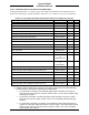


Table Of Contents
- 17001_0_Frt-Matr
- 17001_1_Gen-Info
- 1.1 INTRODUCTION
- 1.2 FUNCTIONAL DESCRIPTION
- 1.2.1 Software Release Summary
- 1.2.2 Transponder Functional Overview
- 1.2.3 GPS Functional Overview
- 1.2.4 Lightning Detection (optional)
- 1.2.5 ADS-B System Overview
- 1.2.6 Traffic Display Functional Overview
- 1.2.7 FISB System Overview
- 1.2.8 Traffic Awareness System (option) Overview
- 1.2.9 ADS-B Traffic Advisory System Overview (optional)
- 1.2.10 Traffic Alert and Collision Avoidance System (option) Overview
- 1.2.11 Terrain Awareness and Warning System Overview (optional)
- 1.2.12 TerrainVisionTM
- 1.2.13 Discrete Inputs and Outputs Functional Overview
- 1.3 EQUIPMENT DESCRIPTIONS
- 1.4 INTERFACES
- 1.4.1 ADS-B Out Fail
- 1.4.2 AHRS Input
- 1.4.3 Altitude Encoder Input
- 1.4.4 Audio Out
- 1.4.5 Standby Mode
- 1.4.6 Audio Mute In and Out
- 1.4.7 Audio Acknowledge
- 1.4.8 RF Suppression Input/output
- 1.4.9 Traffic Alert
- 1.4.10 TAWS Caution and Warning Alert
- 1.4.11 WiFi Interface
- 1.4.12 WOW Input
- 1.4.13 Maintenance Interface
- 1.4.14 GPS Antenna
- 1.4.15 L-Band (978/1030/1090 MHz) Antenna
- 1.4.16 Directional Antenna
- 1.4.17 Traffic Display
- 1.4.18 Weather Display
- 1.4.19 Lightning Detection (WX-500)
- 1.4.20 Control Panel
- 1.5 INSTALLATION CONSIDERATIONS
- 1.6 SPECIFICATIONS
- 1.7 TSO INFORMATION
- 1.8 MODIFICATIONS
- 1.9 SOFTWARE REVISIONS
- 1.10 EQUIPMENT REQUIRED NOT SUPPLIED
- 1.11 EQUIPMENT INTERFACES
- 1.12 OBTAINING SOFTWARE
- 1.13 INSTALLATION PROCEDURE FOR LYNXMSS USB DRIVER
- 1.14 INSTALLATION APPROVAL AND LIMITATIONS
- 17001_2_Instal
- 2.1 INTRODUCTION
- 2.2 UNPACKING AND INSPECTING
- 2.3 INSTALLATION PROCEDURES
- 2.3.1 Panel Mount Location
- 2.3.2 Remote Mount Location
- 2.3.3 Electrical Connections
- 2.3.4 Compatible Equipment Installation Information
- 2.3.5 Discrete Inputs and Output Connections
- 2.3.6 Installation Guidelines for the DCM
- 2.3.7 P1 Mating Connector Assembly
- 2.3.8 Panel mount NGT-9000 Installation
- 2.3.9 Remote Mounted Lynx NGT-9000 Installation
- 2.3.10 CP-2500 Installation Guidelines
- 2.3.11 Antenna Installation Guidelines
- 17001_3_Inst_Check
- 3.1 INTRODUCTION
- 3.2 BASIC OPERATION
- 3.3 MPC (MAT) OPERATION
- 3.4 INSTALLATION PROCEDURE FOR LYNXMSS USB DRIVER
- 3.5 MAINTENANCE MODE
- 3.6 VERIFY SOFTWARE VERSION
- 3.7 SELECT CONFIGURATION OPTIONS
- 3.8 CALIBRATION SETUP
- 3.9 INTERFACE CHECK
- 3.10 SETUP PIM-9000 WIFI MODULE
- 3.11 INSTALLATION CHECKOUT
- 3.11.1 Functional Checks
- 3.11.2 Ground Checks
- 3.11.3 Electromagnetic Interference (E.M.I.) Check
- 3.11.4 Panel mount NGT-9000 Display Check
- 3.11.5 Flight Test
- 3.11.6 Installation Checkout Complete
- 17001_4_Maint
- 17001_5_App-A_signal
- A.1 INTRODUCTION
- A.2 INPUT AND OUTPUT INTERFACES
- A.2.1 Input Power
- A.2.2 RF Suppression Bus
- A.2.3 Audio Output
- A.2.4 Gillham Input (Altitude Input)
- A.2.5 RS-232 Interface
- A.2.6 RS-422 Interface
- A.2.7 ARINC 429 Input
- A.2.8 ARINC 429 Output
- A.2.9 Discrete Input
- A.2.10 Discrete Output
- A.2.11 I2C Serial Bus (Detachable Configuration Module)
- A.2.12 Antenna Connections
- A.3 PIN DEFINITION SUMMARY
- A.4 [J1 CONNECTOR]
- 17001_6_App-B_Environmental
- 17001_7_App-C_Compatibility
- 17001_8_App-D_TSO
- 17001_9_App-E_Questionaire

Lynx NGT-9000
Installation Manual
0040-17001-01 (Revision W) General Information Page 1-35
1.10.2 Installation Kits for the Remote Mount Lynx NGT-9000R
Ordering Installation Kits is a customer option. Item numbers are identified in the installation section.
Refer to the following for ordering information. See Table 1-13, Table 1-14, Table 1-15 or for a list of
components.
Table 1-13: Remote Mount Installation Kit P/N 9060-17500-01 for Straight RF Connector
DESCRIPTION PART NUMBER QTY ITEM
Mounting Tray Assembly NGT-9000 Remote Mount 9002018-001 1 1
Rear Plate Panel Mount Rack 9000-17025-02 1 2
Screw P F100 4-40 X .438 ALY Steel Cad NAS514-P-440-7 4 3
Screw P F100 4-40 X .312 ALY Steel Cad NAS514-P-440-5 4 4
Floating Nut Plate D-Sub Shell Size 3 9000-17036-01 1 5
Floating Nut Plate D-Sub Shell Size 5 9000-17034-01 1 6
Screw F100 2-56 X .250 SS Pass W/ Vibra-tite 2000-10085-01 8 7
Enclosed Backshell, Shell Size 5 9010-17012-01 1 9
Wire Clamp 9000-17076-01 2 10
Contact Socket Crimp Size 22d M39029/57-354 78 11
Assembly Connector D-Sub 78 Position Float Mount 9080-17006-01 1 14
Assembly Connector D-Sub 5 Position 5w5 Float Mount 9080-17007-01
or
9080-17011-01
1 15
Grounding Clip 9002463-001
or
9001963-001
1 16
Screw 4-40 X .312 Pass W/ Vibra-tite 2000-10087-01 10 22
Cable Assembly, Size 8 Straight Plug with BNC Jack
(1)
9020-17009-01 1 23
Float RF Backshell 5w5 D-Sub Shell Size 3 9000-17106-01 1 24
Cable Tie 4.1x0.098 NYL 6.6 Black Low Pro 1040-10002-01 15 26
Cable Ground Strap 9020-17002-01 2 27
Wire Clamp Pad 9000-17132-01 2 30
Cable Assembly, Size 8 Straight Plug with TNC Jack
(1)
9020-17008-01 1 31
Note:
(1) Additional cable assemblies are required for NGT-9000R+ (TAS/TCAS), NGT-9000RD
(Diversity), and NGT-9000RD+ (TAS/TCAS and Diversity) as detailed below:
• For TAS/TCAS functionality, three additional (pigtail) cable assemblies are required for
active traffic directional antenna connection. Refer to Table 1-18 for a list of available cable
assembly part numbers.
• For Diversity functionality, one additional (pigtail) cable assembly is required for upper L-
Band antenna connection. Refer to Table 1-18 for a list of available cable assembly part
numbers.
• For TAS/TCAS and Diversity functionality, three additional (pigtail) cable assemblies are
required for active traffic directional antenna connection. (Note - the TAS/TCAS directional
antenna is also used as the diversity antenna.) Refer to Table 1-18 for a list of available
cable assembly part numbers.