
Installation Manual


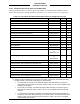


Table Of Contents
- 17001_0_Frt-Matr
- 17001_1_Gen-Info
- 1.1 INTRODUCTION
- 1.2 FUNCTIONAL DESCRIPTION
- 1.2.1 Software Release Summary
- 1.2.2 Transponder Functional Overview
- 1.2.3 GPS Functional Overview
- 1.2.4 Lightning Detection (optional)
- 1.2.5 ADS-B System Overview
- 1.2.6 Traffic Display Functional Overview
- 1.2.7 FISB System Overview
- 1.2.8 Traffic Awareness System (option) Overview
- 1.2.9 ADS-B Traffic Advisory System Overview (optional)
- 1.2.10 Traffic Alert and Collision Avoidance System (option) Overview
- 1.2.11 Terrain Awareness and Warning System Overview (optional)
- 1.2.12 TerrainVisionTM
- 1.2.13 Discrete Inputs and Outputs Functional Overview
- 1.3 EQUIPMENT DESCRIPTIONS
- 1.4 INTERFACES
- 1.4.1 ADS-B Out Fail
- 1.4.2 AHRS Input
- 1.4.3 Altitude Encoder Input
- 1.4.4 Audio Out
- 1.4.5 Standby Mode
- 1.4.6 Audio Mute In and Out
- 1.4.7 Audio Acknowledge
- 1.4.8 RF Suppression Input/output
- 1.4.9 Traffic Alert
- 1.4.10 TAWS Caution and Warning Alert
- 1.4.11 WiFi Interface
- 1.4.12 WOW Input
- 1.4.13 Maintenance Interface
- 1.4.14 GPS Antenna
- 1.4.15 L-Band (978/1030/1090 MHz) Antenna
- 1.4.16 Directional Antenna
- 1.4.17 Traffic Display
- 1.4.18 Weather Display
- 1.4.19 Lightning Detection (WX-500)
- 1.4.20 Control Panel
- 1.5 INSTALLATION CONSIDERATIONS
- 1.6 SPECIFICATIONS
- 1.7 TSO INFORMATION
- 1.8 MODIFICATIONS
- 1.9 SOFTWARE REVISIONS
- 1.10 EQUIPMENT REQUIRED NOT SUPPLIED
- 1.11 EQUIPMENT INTERFACES
- 1.12 OBTAINING SOFTWARE
- 1.13 INSTALLATION PROCEDURE FOR LYNXMSS USB DRIVER
- 1.14 INSTALLATION APPROVAL AND LIMITATIONS
- 17001_2_Instal
- 2.1 INTRODUCTION
- 2.2 UNPACKING AND INSPECTING
- 2.3 INSTALLATION PROCEDURES
- 2.3.1 Panel Mount Location
- 2.3.2 Remote Mount Location
- 2.3.3 Electrical Connections
- 2.3.4 Compatible Equipment Installation Information
- 2.3.5 Discrete Inputs and Output Connections
- 2.3.6 Installation Guidelines for the DCM
- 2.3.7 P1 Mating Connector Assembly
- 2.3.8 Panel mount NGT-9000 Installation
- 2.3.9 Remote Mounted Lynx NGT-9000 Installation
- 2.3.10 CP-2500 Installation Guidelines
- 2.3.11 Antenna Installation Guidelines
- 17001_3_Inst_Check
- 3.1 INTRODUCTION
- 3.2 BASIC OPERATION
- 3.3 MPC (MAT) OPERATION
- 3.4 INSTALLATION PROCEDURE FOR LYNXMSS USB DRIVER
- 3.5 MAINTENANCE MODE
- 3.6 VERIFY SOFTWARE VERSION
- 3.7 SELECT CONFIGURATION OPTIONS
- 3.8 CALIBRATION SETUP
- 3.9 INTERFACE CHECK
- 3.10 SETUP PIM-9000 WIFI MODULE
- 3.11 INSTALLATION CHECKOUT
- 3.11.1 Functional Checks
- 3.11.2 Ground Checks
- 3.11.3 Electromagnetic Interference (E.M.I.) Check
- 3.11.4 Panel mount NGT-9000 Display Check
- 3.11.5 Flight Test
- 3.11.6 Installation Checkout Complete
- 17001_4_Maint
- 17001_5_App-A_signal
- A.1 INTRODUCTION
- A.2 INPUT AND OUTPUT INTERFACES
- A.2.1 Input Power
- A.2.2 RF Suppression Bus
- A.2.3 Audio Output
- A.2.4 Gillham Input (Altitude Input)
- A.2.5 RS-232 Interface
- A.2.6 RS-422 Interface
- A.2.7 ARINC 429 Input
- A.2.8 ARINC 429 Output
- A.2.9 Discrete Input
- A.2.10 Discrete Output
- A.2.11 I2C Serial Bus (Detachable Configuration Module)
- A.2.12 Antenna Connections
- A.3 PIN DEFINITION SUMMARY
- A.4 [J1 CONNECTOR]
- 17001_6_App-B_Environmental
- 17001_7_App-C_Compatibility
- 17001_8_App-D_TSO
- 17001_9_App-E_Questionaire

Lynx NGT-9000
Installation Manual
0040-17001-01 (Revision W) General Information Page 1-31
Table 1-10: Equipment List
ITEM DESCRIPTION
Installation Tools: Twisted Shield Wire Stripper Tool:
Used for preparing wires for the P1 mating connector.
• EDMO Distributors, TSK7000QC
Crimp Hand Tools:
• Crimp Tool: M22520/2-01. For mating connector (P1)
Positioner M22520/2-06
Insert / Extract M81969/1-02
• Crimp Tool: M22520/5-01. For coaxial contact shield crimp termination.
Die Set (HX4) Insert M22520/5-05 (hex crimp die is .213 flat-to-flat)
• Coax Removal Tool: Daniels Manufacturing Corp. (DMC) P/N DRK38
Tools can be purchased from:
Amphenol Industrial; 40-60 Delaware Avenue; Sidney, NY 13838
Phone: 800-678-0141 Fax: 607-563-5157
Panel Retainer Tool:
• Allen Hex Socket Screwdriver, 3/32 head.
Used to secure and remove the unit from the rack.
Installation Kits: The following installation kits are available. PIM-9000 and Antenna Cables are
optional. The Panel and Remote install kits come with the order. Additional RF
Adaptor Cables for Lynx NGT-9000 models (+, D, D+, R+, RD, or RD+) will
need to be ordered. Refer to the following paragraph for ordering information
and a list of components:
• Panel Mount NGT-9000, Paragraph 1.10.1
• Remote Mount NGT-9000R, Paragraph 1.10.2
• PIM-9000, paragraph 1.10.3
• Antenna Cables, paragraph 1.10.4
Software:
Software can be obtained over the ACSS website.
Refer to paragraph 1.12 for
details on the different software available and on how to obtain a copy or
Contact ACSS Field Service for more information.
Lynx Maintenance Application Tool (MPC (MAT))
This tool used for diagnostics, set up configuration options, and software
downloading. The tool is only available to an ACSS Authorized Installer. The
software is bundled with software releases.
LynxMSS USB Drivers and USB Driver Installation Utility
A USB driver is required for communication between the MPC and the Lynx
NGT-9000 via the USB interface. The software is bundled with software
releases.
Procedures to install the LynxMSS USB Driver are found in paragraph 3.4.
WinZip 22
Used to unzip the S/W and MPC files. This software is free from the web.