
Installation Manual


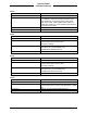

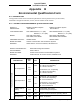


Table Of Contents
- 17001_0_Frt-Matr
- 17001_1_Gen-Info
- 1.1 INTRODUCTION
- 1.2 FUNCTIONAL DESCRIPTION
- 1.2.1 Software Release Summary
- 1.2.2 Transponder Functional Overview
- 1.2.3 GPS Functional Overview
- 1.2.4 Lightning Detection (optional)
- 1.2.5 ADS-B System Overview
- 1.2.6 Traffic Display Functional Overview
- 1.2.7 FISB System Overview
- 1.2.8 Traffic Awareness System (option) Overview
- 1.2.9 ADS-B Traffic Advisory System Overview (optional)
- 1.2.10 Traffic Alert and Collision Avoidance System (option) Overview
- 1.2.11 Terrain Awareness and Warning System Overview (optional)
- 1.2.12 TerrainVisionTM
- 1.2.13 Discrete Inputs and Outputs Functional Overview
- 1.3 EQUIPMENT DESCRIPTIONS
- 1.4 INTERFACES
- 1.4.1 ADS-B Out Fail
- 1.4.2 AHRS Input
- 1.4.3 Altitude Encoder Input
- 1.4.4 Audio Out
- 1.4.5 Standby Mode
- 1.4.6 Audio Mute In and Out
- 1.4.7 Audio Acknowledge
- 1.4.8 RF Suppression Input/output
- 1.4.9 Traffic Alert
- 1.4.10 TAWS Caution and Warning Alert
- 1.4.11 WiFi Interface
- 1.4.12 WOW Input
- 1.4.13 Maintenance Interface
- 1.4.14 GPS Antenna
- 1.4.15 L-Band (978/1030/1090 MHz) Antenna
- 1.4.16 Directional Antenna
- 1.4.17 Traffic Display
- 1.4.18 Weather Display
- 1.4.19 Lightning Detection (WX-500)
- 1.4.20 Control Panel
- 1.5 INSTALLATION CONSIDERATIONS
- 1.6 SPECIFICATIONS
- 1.7 TSO INFORMATION
- 1.8 MODIFICATIONS
- 1.9 SOFTWARE REVISIONS
- 1.10 EQUIPMENT REQUIRED NOT SUPPLIED
- 1.11 EQUIPMENT INTERFACES
- 1.12 OBTAINING SOFTWARE
- 1.13 INSTALLATION PROCEDURE FOR LYNXMSS USB DRIVER
- 1.14 INSTALLATION APPROVAL AND LIMITATIONS
- 17001_2_Instal
- 2.1 INTRODUCTION
- 2.2 UNPACKING AND INSPECTING
- 2.3 INSTALLATION PROCEDURES
- 2.3.1 Panel Mount Location
- 2.3.2 Remote Mount Location
- 2.3.3 Electrical Connections
- 2.3.4 Compatible Equipment Installation Information
- 2.3.5 Discrete Inputs and Output Connections
- 2.3.6 Installation Guidelines for the DCM
- 2.3.7 P1 Mating Connector Assembly
- 2.3.8 Panel mount NGT-9000 Installation
- 2.3.9 Remote Mounted Lynx NGT-9000 Installation
- 2.3.10 CP-2500 Installation Guidelines
- 2.3.11 Antenna Installation Guidelines
- 17001_3_Inst_Check
- 3.1 INTRODUCTION
- 3.2 BASIC OPERATION
- 3.3 MPC (MAT) OPERATION
- 3.4 INSTALLATION PROCEDURE FOR LYNXMSS USB DRIVER
- 3.5 MAINTENANCE MODE
- 3.6 VERIFY SOFTWARE VERSION
- 3.7 SELECT CONFIGURATION OPTIONS
- 3.8 CALIBRATION SETUP
- 3.9 INTERFACE CHECK
- 3.10 SETUP PIM-9000 WIFI MODULE
- 3.11 INSTALLATION CHECKOUT
- 3.11.1 Functional Checks
- 3.11.2 Ground Checks
- 3.11.3 Electromagnetic Interference (E.M.I.) Check
- 3.11.4 Panel mount NGT-9000 Display Check
- 3.11.5 Flight Test
- 3.11.6 Installation Checkout Complete
- 17001_4_Maint
- 17001_5_App-A_signal
- A.1 INTRODUCTION
- A.2 INPUT AND OUTPUT INTERFACES
- A.2.1 Input Power
- A.2.2 RF Suppression Bus
- A.2.3 Audio Output
- A.2.4 Gillham Input (Altitude Input)
- A.2.5 RS-232 Interface
- A.2.6 RS-422 Interface
- A.2.7 ARINC 429 Input
- A.2.8 ARINC 429 Output
- A.2.9 Discrete Input
- A.2.10 Discrete Output
- A.2.11 I2C Serial Bus (Detachable Configuration Module)
- A.2.12 Antenna Connections
- A.3 PIN DEFINITION SUMMARY
- A.4 [J1 CONNECTOR]
- 17001_6_App-B_Environmental
- 17001_7_App-C_Compatibility
- 17001_8_App-D_TSO
- 17001_9_App-E_Questionaire

Lynx NGT-9000
Installation Manual
0040-17001-01 (Revision W) Appendix C Page C-1
Appendix
C
Equipment Compatibility and Diagrams
C.1 INTRODUCTION
This information should be used in conjunction with the primary interconnect drawing in the installation
section of this manual, as well as the display and equipment manufacturers installation instructions in the
applicable installation manual. Refer to Section 1 – Paragraph 1.11 for details on the equipment listed in
this appendix.
C.2 TRAFFIC DISPLAYS
MANUFACTURER MODEL DATA FORMAT NOTES
Aspen EFD1000 PFD
EFD1000 MFD
EFD500 MFD
See Figure C-1
RS-422
RS-232
SW Version
MAP SW 2.8.1 or later
IOP SW2.0.5 or later
910-00001-XXX (except -004)
(Set RS-422 Baud Rate on
MPC (MAT) for 115200)
Avidyne IFD-4xx / 5xx
See Figure C-6
RS-232 SW 10.2.0.0
(3)
SW 10.2.x
(4)
Avidyne EX5000
Figure C-9
ARINC 429 SW 8.2 or later
Bendix/King KMD 550/850
(2)
See Figure C-7
ARINC 429 SW Version – 02/02
Garmin GMX 200
(1)
With Traffic I/O
See Figure C-2
RS-422
ARINC 429
SW Version 2.13
If Traffic I/O is installed, either the RS-422 or
ARINC 429 may be used for display of traffic.
Garmin MX 20
(1)
With Traffic I/O
See Figure C-2
RS-422
ARINC 429
SW Version– 5.7
If Traffic I/O is installed, either the RS-422 or
ARINC 429 may be used for display of traffic.
Garmin
(5)
GNS 430W/530W
GNS 430/530
See Figure C-3
ARINC 429 (Standard traffic only.)
5.0 GPS SW / Version 5.10
Garmin
(5)
G500/600
See Figure C-4
ARINC 429 (Standard traffic only)
GDU-620 Version 6.11 FPGA
and I/O Version – 2.1
Garmin
(5)
GTN 650/750
See Figure C-5
ARINC 429 (Standard traffic only)
4.0 GPS / SW Version – 5.0
6.11 GPS / SW Version – 5.0
Genesys IDU-450
IDU-680
See Figure C-8
RS-422 EFIS Version 8.0F and later
Note:
(1) If Traffic I/O is installed, either the RS-422 or ARINC 429 may be used for display of traffic.
(2) Requires either ATAS, TAS or TCAS enabled in order to be compatible.
(3) An Aspen display and the IFD-4xx / 5xx Software level 10.2.1 or higher can both be connected to the NGT-9000.
(4) The IFD-4xx / 5xx RS232 in setting of Capstone HS Trfc+Wx is 115.2 Kb rate compatible with the Aspen. Versions
earlier than 10.2.1 support 38.4 Kb only. Wiring is RS-422 output from NGT-9000 to an RS-232 input on the IFD-
4xx/5xx.
(5) No weather is displayed on Garmin displays.