
Installation Manual


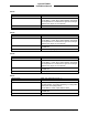

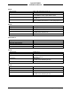


Table Of Contents
- 17001_0_Frt-Matr
- 17001_1_Gen-Info
- 1.1 INTRODUCTION
- 1.2 FUNCTIONAL DESCRIPTION
- 1.2.1 Software Release Summary
- 1.2.2 Transponder Functional Overview
- 1.2.3 GPS Functional Overview
- 1.2.4 Lightning Detection (optional)
- 1.2.5 ADS-B System Overview
- 1.2.6 Traffic Display Functional Overview
- 1.2.7 FISB System Overview
- 1.2.8 Traffic Awareness System (option) Overview
- 1.2.9 ADS-B Traffic Advisory System Overview (optional)
- 1.2.10 Traffic Alert and Collision Avoidance System (option) Overview
- 1.2.11 Terrain Awareness and Warning System Overview (optional)
- 1.2.12 TerrainVisionTM
- 1.2.13 Discrete Inputs and Outputs Functional Overview
- 1.3 EQUIPMENT DESCRIPTIONS
- 1.4 INTERFACES
- 1.4.1 ADS-B Out Fail
- 1.4.2 AHRS Input
- 1.4.3 Altitude Encoder Input
- 1.4.4 Audio Out
- 1.4.5 Standby Mode
- 1.4.6 Audio Mute In and Out
- 1.4.7 Audio Acknowledge
- 1.4.8 RF Suppression Input/output
- 1.4.9 Traffic Alert
- 1.4.10 TAWS Caution and Warning Alert
- 1.4.11 WiFi Interface
- 1.4.12 WOW Input
- 1.4.13 Maintenance Interface
- 1.4.14 GPS Antenna
- 1.4.15 L-Band (978/1030/1090 MHz) Antenna
- 1.4.16 Directional Antenna
- 1.4.17 Traffic Display
- 1.4.18 Weather Display
- 1.4.19 Lightning Detection (WX-500)
- 1.4.20 Control Panel
- 1.5 INSTALLATION CONSIDERATIONS
- 1.6 SPECIFICATIONS
- 1.7 TSO INFORMATION
- 1.8 MODIFICATIONS
- 1.9 SOFTWARE REVISIONS
- 1.10 EQUIPMENT REQUIRED NOT SUPPLIED
- 1.11 EQUIPMENT INTERFACES
- 1.12 OBTAINING SOFTWARE
- 1.13 INSTALLATION PROCEDURE FOR LYNXMSS USB DRIVER
- 1.14 INSTALLATION APPROVAL AND LIMITATIONS
- 17001_2_Instal
- 2.1 INTRODUCTION
- 2.2 UNPACKING AND INSPECTING
- 2.3 INSTALLATION PROCEDURES
- 2.3.1 Panel Mount Location
- 2.3.2 Remote Mount Location
- 2.3.3 Electrical Connections
- 2.3.4 Compatible Equipment Installation Information
- 2.3.5 Discrete Inputs and Output Connections
- 2.3.6 Installation Guidelines for the DCM
- 2.3.7 P1 Mating Connector Assembly
- 2.3.8 Panel mount NGT-9000 Installation
- 2.3.9 Remote Mounted Lynx NGT-9000 Installation
- 2.3.10 CP-2500 Installation Guidelines
- 2.3.11 Antenna Installation Guidelines
- 17001_3_Inst_Check
- 3.1 INTRODUCTION
- 3.2 BASIC OPERATION
- 3.3 MPC (MAT) OPERATION
- 3.4 INSTALLATION PROCEDURE FOR LYNXMSS USB DRIVER
- 3.5 MAINTENANCE MODE
- 3.6 VERIFY SOFTWARE VERSION
- 3.7 SELECT CONFIGURATION OPTIONS
- 3.8 CALIBRATION SETUP
- 3.9 INTERFACE CHECK
- 3.10 SETUP PIM-9000 WIFI MODULE
- 3.11 INSTALLATION CHECKOUT
- 3.11.1 Functional Checks
- 3.11.2 Ground Checks
- 3.11.3 Electromagnetic Interference (E.M.I.) Check
- 3.11.4 Panel mount NGT-9000 Display Check
- 3.11.5 Flight Test
- 3.11.6 Installation Checkout Complete
- 17001_4_Maint
- 17001_5_App-A_signal
- A.1 INTRODUCTION
- A.2 INPUT AND OUTPUT INTERFACES
- A.2.1 Input Power
- A.2.2 RF Suppression Bus
- A.2.3 Audio Output
- A.2.4 Gillham Input (Altitude Input)
- A.2.5 RS-232 Interface
- A.2.6 RS-422 Interface
- A.2.7 ARINC 429 Input
- A.2.8 ARINC 429 Output
- A.2.9 Discrete Input
- A.2.10 Discrete Output
- A.2.11 I2C Serial Bus (Detachable Configuration Module)
- A.2.12 Antenna Connections
- A.3 PIN DEFINITION SUMMARY
- A.4 [J1 CONNECTOR]
- 17001_6_App-B_Environmental
- 17001_7_App-C_Compatibility
- 17001_8_App-D_TSO
- 17001_9_App-E_Questionaire

Lynx NGT-9000
Installation Manual
0040-17001-01 (Revision W) Appendix A Page A-18
PIN 32
Signal Name:
DISC_IN6 (Discrete Input No. 6)
Signal Function:
Standby Mode
Electrical Characteristics:
GND/Open (GND active)
Ground State ≤ 3.5Vdc, Open State ≥ 18Vdc
Connection:
Locking Switch
24 AWG wire
Comments:
Optional. Used to place the unit’s transponder in Standby
Mode. Available with Release 2.1. See paragraph A.2.9.
PIN 33
Signal Name:
SUPPR_BUS
Signal Function:
RF Suppression Output
Electrical Characteristics:
See paragraph A.2.2
Connection:
Aircraft Suppression Bus
24 AWG twisted shielded wire
Comments:
PIN 34 thru 37
Signal Name: Spare
Signal Function:
Spare pin
Electrical Characteristics:
---
Connection:
No Connection
Comments:
PIN 38
Signal Name:
AUDIO OUT
Signal Function:
Audio Out 600 Ohm H
Electrical Characteristics:
40 milli Watts (RMS) at 1000 Hz into a 600 Ohm audio
distribution system.
Connection: Audio Panel
24 AWG twisted shielded pair wire
Comments:
See paragraph A.2.3
PIN 39
Signal Name: GROUND
Signal Function:
Audio Out 600 Ohm L
Electrical Characteristics:
Ground
Connection:
Audio Panel
24 AWG twisted shielded pair wire
Comments:
See paragraph A.2.3