
Installation Manual


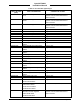
Table Of Contents
- 17001_0_Frt-Matr
- 17001_1_Gen-Info
- 1.1 INTRODUCTION
- 1.2 FUNCTIONAL DESCRIPTION
- 1.2.1 Software Release Summary
- 1.2.2 Transponder Functional Overview
- 1.2.3 GPS Functional Overview
- 1.2.4 Lightning Detection (optional)
- 1.2.5 ADS-B System Overview
- 1.2.6 Traffic Display Functional Overview
- 1.2.7 FISB System Overview
- 1.2.8 Traffic Awareness System (option) Overview
- 1.2.9 ADS-B Traffic Advisory System Overview (optional)
- 1.2.10 Traffic Alert and Collision Avoidance System (option) Overview
- 1.2.11 Terrain Awareness and Warning System Overview (optional)
- 1.2.12 TerrainVisionTM
- 1.2.13 Discrete Inputs and Outputs Functional Overview
- 1.3 EQUIPMENT DESCRIPTIONS
- 1.4 INTERFACES
- 1.4.1 ADS-B Out Fail
- 1.4.2 AHRS Input
- 1.4.3 Altitude Encoder Input
- 1.4.4 Audio Out
- 1.4.5 Standby Mode
- 1.4.6 Audio Mute In and Out
- 1.4.7 Audio Acknowledge
- 1.4.8 RF Suppression Input/output
- 1.4.9 Traffic Alert
- 1.4.10 TAWS Caution and Warning Alert
- 1.4.11 WiFi Interface
- 1.4.12 WOW Input
- 1.4.13 Maintenance Interface
- 1.4.14 GPS Antenna
- 1.4.15 L-Band (978/1030/1090 MHz) Antenna
- 1.4.16 Directional Antenna
- 1.4.17 Traffic Display
- 1.4.18 Weather Display
- 1.4.19 Lightning Detection (WX-500)
- 1.4.20 Control Panel
- 1.5 INSTALLATION CONSIDERATIONS
- 1.6 SPECIFICATIONS
- 1.7 TSO INFORMATION
- 1.8 MODIFICATIONS
- 1.9 SOFTWARE REVISIONS
- 1.10 EQUIPMENT REQUIRED NOT SUPPLIED
- 1.11 EQUIPMENT INTERFACES
- 1.12 OBTAINING SOFTWARE
- 1.13 INSTALLATION PROCEDURE FOR LYNXMSS USB DRIVER
- 1.14 INSTALLATION APPROVAL AND LIMITATIONS
- 17001_2_Instal
- 2.1 INTRODUCTION
- 2.2 UNPACKING AND INSPECTING
- 2.3 INSTALLATION PROCEDURES
- 2.3.1 Panel Mount Location
- 2.3.2 Remote Mount Location
- 2.3.3 Electrical Connections
- 2.3.4 Compatible Equipment Installation Information
- 2.3.5 Discrete Inputs and Output Connections
- 2.3.6 Installation Guidelines for the DCM
- 2.3.7 P1 Mating Connector Assembly
- 2.3.8 Panel mount NGT-9000 Installation
- 2.3.9 Remote Mounted Lynx NGT-9000 Installation
- 2.3.10 CP-2500 Installation Guidelines
- 2.3.11 Antenna Installation Guidelines
- 17001_3_Inst_Check
- 3.1 INTRODUCTION
- 3.2 BASIC OPERATION
- 3.3 MPC (MAT) OPERATION
- 3.4 INSTALLATION PROCEDURE FOR LYNXMSS USB DRIVER
- 3.5 MAINTENANCE MODE
- 3.6 VERIFY SOFTWARE VERSION
- 3.7 SELECT CONFIGURATION OPTIONS
- 3.8 CALIBRATION SETUP
- 3.9 INTERFACE CHECK
- 3.10 SETUP PIM-9000 WIFI MODULE
- 3.11 INSTALLATION CHECKOUT
- 3.11.1 Functional Checks
- 3.11.2 Ground Checks
- 3.11.3 Electromagnetic Interference (E.M.I.) Check
- 3.11.4 Panel mount NGT-9000 Display Check
- 3.11.5 Flight Test
- 3.11.6 Installation Checkout Complete
- 17001_4_Maint
- 17001_5_App-A_signal
- A.1 INTRODUCTION
- A.2 INPUT AND OUTPUT INTERFACES
- A.2.1 Input Power
- A.2.2 RF Suppression Bus
- A.2.3 Audio Output
- A.2.4 Gillham Input (Altitude Input)
- A.2.5 RS-232 Interface
- A.2.6 RS-422 Interface
- A.2.7 ARINC 429 Input
- A.2.8 ARINC 429 Output
- A.2.9 Discrete Input
- A.2.10 Discrete Output
- A.2.11 I2C Serial Bus (Detachable Configuration Module)
- A.2.12 Antenna Connections
- A.3 PIN DEFINITION SUMMARY
- A.4 [J1 CONNECTOR]
- 17001_6_App-B_Environmental
- 17001_7_App-C_Compatibility
- 17001_8_App-D_TSO
- 17001_9_App-E_Questionaire

Lynx NGT-9000
Installation Manual
0040-17001-01 (Revision W) Maintenance Page 4-36
4.5.3.2 Fault Log
The Fault Log can be used for troubleshooting. Each fault is entered on its own indexed row, with details
for date, time, etc. Clicking on a row provides the user with additional information at the top of the page.
This information includes a fault description and a possible description of the loss of functionality.
Buttons on the bottom of the page provide the user the options of ‘Refresh’, ‘Clear’, ‘Filter’, ‘Save’,
‘Load’, and ‘Export to CSV’. The fault data can be cleared at the option of the user.
NOTE
Typically, the fault log should not be cleared unless instructed by ACSS
Field Service personnel.
A saved fault log can be viewed by the MPC (MAT) when the unit is not connected by using the Load
function.
Table 4-4: List of Fault Log Messages
FAULT ID/ CODE
(HEX)
FAULT DESCRIPTION CORRECTIVE ACTION
0x00000001
Kernel Fault Wd Expire
Reboot the unit and check if the fault
persists. Contact ACSS Field Service
before removal.
0x00000002 Kernel Fault Process Term Reboot the unit and check if the fault
persists. Contact ACSS Field Service
before removal.
0x00000003
Kernel Fault Thread Term
Reboot the unit and check if the fault
persists. Contact ACSS Field Service
before removal.
0x00000004
Kernel Fault Thread Timeout
Reboot the unit and check if the fault
persists. Contact ACSS Field Service
before removal.
0x00000005 Kernel Fault Trap Reboot the unit and check if the fault
persists. Contact ACSS Field Service
before removal.
0x00000006
Kernel Fault BIT Wd
Reboot the unit and check if the fault
persists. Contact ACSS Field Service
before removal.
0x00000007
Kernel Fault BIT Clock
Reboot the unit and check if the fault
persists. Contact ACSS Field Service
before removal.
0x00000008
Kernel Fault CBIT CRC
Reboot the unit and check if the fault
persists. Contact ACSS Field Service
before removal.
0x00000009
Kernel Fault ISR Limit
Reboot the unit and check if the fault
persists. Contact ACSS Field Service
before removal.
0x0000000A
Kernel Fault CBIT FPGA
Reboot the unit and check if the fault
persists. Contact ACSS Field Service
before removal.
0x0000000B
Kernel Fault CBIT SW Exception
Reboot the unit and check if the fault
persists. Contact ACSS Field Service
before removal.
0x00000021 Touch INIT Fault Reboot the unit and check if the fault
persists. Contact ACSS Field Service
before removal.