
Installation Manual


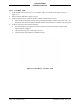
Table Of Contents
- 17001_0_Frt-Matr
- 17001_1_Gen-Info
- 1.1 INTRODUCTION
- 1.2 FUNCTIONAL DESCRIPTION
- 1.2.1 Software Release Summary
- 1.2.2 Transponder Functional Overview
- 1.2.3 GPS Functional Overview
- 1.2.4 Lightning Detection (optional)
- 1.2.5 ADS-B System Overview
- 1.2.6 Traffic Display Functional Overview
- 1.2.7 FISB System Overview
- 1.2.8 Traffic Awareness System (option) Overview
- 1.2.9 ADS-B Traffic Advisory System Overview (optional)
- 1.2.10 Traffic Alert and Collision Avoidance System (option) Overview
- 1.2.11 Terrain Awareness and Warning System Overview (optional)
- 1.2.12 TerrainVisionTM
- 1.2.13 Discrete Inputs and Outputs Functional Overview
- 1.3 EQUIPMENT DESCRIPTIONS
- 1.4 INTERFACES
- 1.4.1 ADS-B Out Fail
- 1.4.2 AHRS Input
- 1.4.3 Altitude Encoder Input
- 1.4.4 Audio Out
- 1.4.5 Standby Mode
- 1.4.6 Audio Mute In and Out
- 1.4.7 Audio Acknowledge
- 1.4.8 RF Suppression Input/output
- 1.4.9 Traffic Alert
- 1.4.10 TAWS Caution and Warning Alert
- 1.4.11 WiFi Interface
- 1.4.12 WOW Input
- 1.4.13 Maintenance Interface
- 1.4.14 GPS Antenna
- 1.4.15 L-Band (978/1030/1090 MHz) Antenna
- 1.4.16 Directional Antenna
- 1.4.17 Traffic Display
- 1.4.18 Weather Display
- 1.4.19 Lightning Detection (WX-500)
- 1.4.20 Control Panel
- 1.5 INSTALLATION CONSIDERATIONS
- 1.6 SPECIFICATIONS
- 1.7 TSO INFORMATION
- 1.8 MODIFICATIONS
- 1.9 SOFTWARE REVISIONS
- 1.10 EQUIPMENT REQUIRED NOT SUPPLIED
- 1.11 EQUIPMENT INTERFACES
- 1.12 OBTAINING SOFTWARE
- 1.13 INSTALLATION PROCEDURE FOR LYNXMSS USB DRIVER
- 1.14 INSTALLATION APPROVAL AND LIMITATIONS
- 17001_2_Instal
- 2.1 INTRODUCTION
- 2.2 UNPACKING AND INSPECTING
- 2.3 INSTALLATION PROCEDURES
- 2.3.1 Panel Mount Location
- 2.3.2 Remote Mount Location
- 2.3.3 Electrical Connections
- 2.3.4 Compatible Equipment Installation Information
- 2.3.5 Discrete Inputs and Output Connections
- 2.3.6 Installation Guidelines for the DCM
- 2.3.7 P1 Mating Connector Assembly
- 2.3.8 Panel mount NGT-9000 Installation
- 2.3.9 Remote Mounted Lynx NGT-9000 Installation
- 2.3.10 CP-2500 Installation Guidelines
- 2.3.11 Antenna Installation Guidelines
- 17001_3_Inst_Check
- 3.1 INTRODUCTION
- 3.2 BASIC OPERATION
- 3.3 MPC (MAT) OPERATION
- 3.4 INSTALLATION PROCEDURE FOR LYNXMSS USB DRIVER
- 3.5 MAINTENANCE MODE
- 3.6 VERIFY SOFTWARE VERSION
- 3.7 SELECT CONFIGURATION OPTIONS
- 3.8 CALIBRATION SETUP
- 3.9 INTERFACE CHECK
- 3.10 SETUP PIM-9000 WIFI MODULE
- 3.11 INSTALLATION CHECKOUT
- 3.11.1 Functional Checks
- 3.11.2 Ground Checks
- 3.11.3 Electromagnetic Interference (E.M.I.) Check
- 3.11.4 Panel mount NGT-9000 Display Check
- 3.11.5 Flight Test
- 3.11.6 Installation Checkout Complete
- 17001_4_Maint
- 17001_5_App-A_signal
- A.1 INTRODUCTION
- A.2 INPUT AND OUTPUT INTERFACES
- A.2.1 Input Power
- A.2.2 RF Suppression Bus
- A.2.3 Audio Output
- A.2.4 Gillham Input (Altitude Input)
- A.2.5 RS-232 Interface
- A.2.6 RS-422 Interface
- A.2.7 ARINC 429 Input
- A.2.8 ARINC 429 Output
- A.2.9 Discrete Input
- A.2.10 Discrete Output
- A.2.11 I2C Serial Bus (Detachable Configuration Module)
- A.2.12 Antenna Connections
- A.3 PIN DEFINITION SUMMARY
- A.4 [J1 CONNECTOR]
- 17001_6_App-B_Environmental
- 17001_7_App-C_Compatibility
- 17001_8_App-D_TSO
- 17001_9_App-E_Questionaire

Lynx NGT-9000
Installation Manual
0040-17001-01 (Revision W) Installation Checkout Page 3-33
3.9.1 Live Data - Discrete Inputs, Altitude, and Heading
1. From the MPC (MAT) select Service > Live Data > Discrete Inputs, Altitude, and Heading. An
example of this page is shown in Figure 3-16.
• Review the information seen on the inputs page.
• The Audio Ack In Active discrete input is available only using the MPC (MAT) 8010-17002-020x
or 8010-17002-030x.
• The True/False indication of the current state of the discrete (e.g., True for the squat on ground
means that the aircraft is on ground. A false would mean that the aircraft was not on the ground,
at least according to the discrete).
Note – when the audio mute discrete is grounded, it is considered active l (i.e. muted). The
Audio Mute In active indication shows "True" when this discrete is active (grounded).
• The Overall Discretes Validity is an indication of the remaining discrete states. A "True"
indicating that these indications are valid. A "False" indication with red text indicates that the
input is not being detected by the unit and a problem exists. If a problem is noted, do the
following.
o Check the configuration setup options for correct settings.
o Check the fault log (Info > Fault Log) for issues.
o Check wiring or equipment.
• Compare the altitude and heading values to an outside source.
Figure 3-16: MPC (MAT) – Live Data – Inputs