
Installation Manual


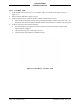
Table Of Contents
- 17001_0_Frt-Matr
- 17001_1_Gen-Info
- 1.1 INTRODUCTION
- 1.2 FUNCTIONAL DESCRIPTION
- 1.2.1 Software Release Summary
- 1.2.2 Transponder Functional Overview
- 1.2.3 GPS Functional Overview
- 1.2.4 Lightning Detection (optional)
- 1.2.5 ADS-B System Overview
- 1.2.6 Traffic Display Functional Overview
- 1.2.7 FISB System Overview
- 1.2.8 Traffic Awareness System (option) Overview
- 1.2.9 ADS-B Traffic Advisory System Overview (optional)
- 1.2.10 Traffic Alert and Collision Avoidance System (option) Overview
- 1.2.11 Terrain Awareness and Warning System Overview (optional)
- 1.2.12 TerrainVisionTM
- 1.2.13 Discrete Inputs and Outputs Functional Overview
- 1.3 EQUIPMENT DESCRIPTIONS
- 1.4 INTERFACES
- 1.4.1 ADS-B Out Fail
- 1.4.2 AHRS Input
- 1.4.3 Altitude Encoder Input
- 1.4.4 Audio Out
- 1.4.5 Standby Mode
- 1.4.6 Audio Mute In and Out
- 1.4.7 Audio Acknowledge
- 1.4.8 RF Suppression Input/output
- 1.4.9 Traffic Alert
- 1.4.10 TAWS Caution and Warning Alert
- 1.4.11 WiFi Interface
- 1.4.12 WOW Input
- 1.4.13 Maintenance Interface
- 1.4.14 GPS Antenna
- 1.4.15 L-Band (978/1030/1090 MHz) Antenna
- 1.4.16 Directional Antenna
- 1.4.17 Traffic Display
- 1.4.18 Weather Display
- 1.4.19 Lightning Detection (WX-500)
- 1.4.20 Control Panel
- 1.5 INSTALLATION CONSIDERATIONS
- 1.6 SPECIFICATIONS
- 1.7 TSO INFORMATION
- 1.8 MODIFICATIONS
- 1.9 SOFTWARE REVISIONS
- 1.10 EQUIPMENT REQUIRED NOT SUPPLIED
- 1.11 EQUIPMENT INTERFACES
- 1.12 OBTAINING SOFTWARE
- 1.13 INSTALLATION PROCEDURE FOR LYNXMSS USB DRIVER
- 1.14 INSTALLATION APPROVAL AND LIMITATIONS
- 17001_2_Instal
- 2.1 INTRODUCTION
- 2.2 UNPACKING AND INSPECTING
- 2.3 INSTALLATION PROCEDURES
- 2.3.1 Panel Mount Location
- 2.3.2 Remote Mount Location
- 2.3.3 Electrical Connections
- 2.3.4 Compatible Equipment Installation Information
- 2.3.5 Discrete Inputs and Output Connections
- 2.3.6 Installation Guidelines for the DCM
- 2.3.7 P1 Mating Connector Assembly
- 2.3.8 Panel mount NGT-9000 Installation
- 2.3.9 Remote Mounted Lynx NGT-9000 Installation
- 2.3.10 CP-2500 Installation Guidelines
- 2.3.11 Antenna Installation Guidelines
- 17001_3_Inst_Check
- 3.1 INTRODUCTION
- 3.2 BASIC OPERATION
- 3.3 MPC (MAT) OPERATION
- 3.4 INSTALLATION PROCEDURE FOR LYNXMSS USB DRIVER
- 3.5 MAINTENANCE MODE
- 3.6 VERIFY SOFTWARE VERSION
- 3.7 SELECT CONFIGURATION OPTIONS
- 3.8 CALIBRATION SETUP
- 3.9 INTERFACE CHECK
- 3.10 SETUP PIM-9000 WIFI MODULE
- 3.11 INSTALLATION CHECKOUT
- 3.11.1 Functional Checks
- 3.11.2 Ground Checks
- 3.11.3 Electromagnetic Interference (E.M.I.) Check
- 3.11.4 Panel mount NGT-9000 Display Check
- 3.11.5 Flight Test
- 3.11.6 Installation Checkout Complete
- 17001_4_Maint
- 17001_5_App-A_signal
- A.1 INTRODUCTION
- A.2 INPUT AND OUTPUT INTERFACES
- A.2.1 Input Power
- A.2.2 RF Suppression Bus
- A.2.3 Audio Output
- A.2.4 Gillham Input (Altitude Input)
- A.2.5 RS-232 Interface
- A.2.6 RS-422 Interface
- A.2.7 ARINC 429 Input
- A.2.8 ARINC 429 Output
- A.2.9 Discrete Input
- A.2.10 Discrete Output
- A.2.11 I2C Serial Bus (Detachable Configuration Module)
- A.2.12 Antenna Connections
- A.3 PIN DEFINITION SUMMARY
- A.4 [J1 CONNECTOR]
- 17001_6_App-B_Environmental
- 17001_7_App-C_Compatibility
- 17001_8_App-D_TSO
- 17001_9_App-E_Questionaire

Lynx NGT-9000
Installation Manual
0040-17001-01 (Revision W) Installation Checkout Page 3-26
e. Resolution (ft): Select > 25 or <=25 based on the encoder increment rate.
• The resolution is automatically changed to > 25 ft. when Gillham Interface source is
selected.
• Selecting > 25 sets the Altitude Thresholds for GPS altitude and Pressure Altitude to 150ft.
• Selecting <=25 sets the Altitude Thresholds for GPS altitude and Pressure Altitude to 50ft.
3. Click on the Apply button after all information is entered. This information is saved to the
configuration module.
4. Ensure the "Write to DCM succeeded. Write to NVM backup succeeded" message is displayed in the
lower communications bar.
3.7.3 I/O Options – Misc
From the MPC (MAT) select Setup…ConfigurationModifyI/O OptionsMisc. See Figure 3-12.
Enter the information specific to the installation for the intended certification.
NGT-9000 NGT-9000R
Figure 3-12: MPC (MAT) – I/O Options – Misc
1. Control Panel: This option is shown as Touch Screen for NGT-9000 or CP-2500 and ARINC 429
(Release 3.2 and later) for NGT-9000R.
• Touch Screen: This is set for Touchscreen for panel mount NGT-9000.
• CP-2500: This option must be selected for the remote mount NGT-9000R installed with a CP-
2500.
• ARINC 429: Only applicable to a remote mount NGT-9000R, this option is selected for
ARINC 429 Control Panels. Note: this option includes Transponder control only.
RS-232 Baud Rate: 9600 baud rate must be selected for the CP-2500 and is normally selected to
9600 for other controllers.