
Installation Manual


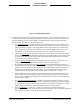
Table Of Contents
- 17001_0_Frt-Matr
- 17001_1_Gen-Info
- 1.1 INTRODUCTION
- 1.2 FUNCTIONAL DESCRIPTION
- 1.2.1 Software Release Summary
- 1.2.2 Transponder Functional Overview
- 1.2.3 GPS Functional Overview
- 1.2.4 Lightning Detection (optional)
- 1.2.5 ADS-B System Overview
- 1.2.6 Traffic Display Functional Overview
- 1.2.7 FISB System Overview
- 1.2.8 Traffic Awareness System (option) Overview
- 1.2.9 ADS-B Traffic Advisory System Overview (optional)
- 1.2.10 Traffic Alert and Collision Avoidance System (option) Overview
- 1.2.11 Terrain Awareness and Warning System Overview (optional)
- 1.2.12 TerrainVisionTM
- 1.2.13 Discrete Inputs and Outputs Functional Overview
- 1.3 EQUIPMENT DESCRIPTIONS
- 1.4 INTERFACES
- 1.4.1 ADS-B Out Fail
- 1.4.2 AHRS Input
- 1.4.3 Altitude Encoder Input
- 1.4.4 Audio Out
- 1.4.5 Standby Mode
- 1.4.6 Audio Mute In and Out
- 1.4.7 Audio Acknowledge
- 1.4.8 RF Suppression Input/output
- 1.4.9 Traffic Alert
- 1.4.10 TAWS Caution and Warning Alert
- 1.4.11 WiFi Interface
- 1.4.12 WOW Input
- 1.4.13 Maintenance Interface
- 1.4.14 GPS Antenna
- 1.4.15 L-Band (978/1030/1090 MHz) Antenna
- 1.4.16 Directional Antenna
- 1.4.17 Traffic Display
- 1.4.18 Weather Display
- 1.4.19 Lightning Detection (WX-500)
- 1.4.20 Control Panel
- 1.5 INSTALLATION CONSIDERATIONS
- 1.6 SPECIFICATIONS
- 1.7 TSO INFORMATION
- 1.8 MODIFICATIONS
- 1.9 SOFTWARE REVISIONS
- 1.10 EQUIPMENT REQUIRED NOT SUPPLIED
- 1.11 EQUIPMENT INTERFACES
- 1.12 OBTAINING SOFTWARE
- 1.13 INSTALLATION PROCEDURE FOR LYNXMSS USB DRIVER
- 1.14 INSTALLATION APPROVAL AND LIMITATIONS
- 17001_2_Instal
- 2.1 INTRODUCTION
- 2.2 UNPACKING AND INSPECTING
- 2.3 INSTALLATION PROCEDURES
- 2.3.1 Panel Mount Location
- 2.3.2 Remote Mount Location
- 2.3.3 Electrical Connections
- 2.3.4 Compatible Equipment Installation Information
- 2.3.5 Discrete Inputs and Output Connections
- 2.3.6 Installation Guidelines for the DCM
- 2.3.7 P1 Mating Connector Assembly
- 2.3.8 Panel mount NGT-9000 Installation
- 2.3.9 Remote Mounted Lynx NGT-9000 Installation
- 2.3.10 CP-2500 Installation Guidelines
- 2.3.11 Antenna Installation Guidelines
- 17001_3_Inst_Check
- 3.1 INTRODUCTION
- 3.2 BASIC OPERATION
- 3.3 MPC (MAT) OPERATION
- 3.4 INSTALLATION PROCEDURE FOR LYNXMSS USB DRIVER
- 3.5 MAINTENANCE MODE
- 3.6 VERIFY SOFTWARE VERSION
- 3.7 SELECT CONFIGURATION OPTIONS
- 3.8 CALIBRATION SETUP
- 3.9 INTERFACE CHECK
- 3.10 SETUP PIM-9000 WIFI MODULE
- 3.11 INSTALLATION CHECKOUT
- 3.11.1 Functional Checks
- 3.11.2 Ground Checks
- 3.11.3 Electromagnetic Interference (E.M.I.) Check
- 3.11.4 Panel mount NGT-9000 Display Check
- 3.11.5 Flight Test
- 3.11.6 Installation Checkout Complete
- 17001_4_Maint
- 17001_5_App-A_signal
- A.1 INTRODUCTION
- A.2 INPUT AND OUTPUT INTERFACES
- A.2.1 Input Power
- A.2.2 RF Suppression Bus
- A.2.3 Audio Output
- A.2.4 Gillham Input (Altitude Input)
- A.2.5 RS-232 Interface
- A.2.6 RS-422 Interface
- A.2.7 ARINC 429 Input
- A.2.8 ARINC 429 Output
- A.2.9 Discrete Input
- A.2.10 Discrete Output
- A.2.11 I2C Serial Bus (Detachable Configuration Module)
- A.2.12 Antenna Connections
- A.3 PIN DEFINITION SUMMARY
- A.4 [J1 CONNECTOR]
- 17001_6_App-B_Environmental
- 17001_7_App-C_Compatibility
- 17001_8_App-D_TSO
- 17001_9_App-E_Questionaire

Lynx NGT-9000
Installation Manual
0040-17001-01 (Revision W) Installation Checkout Page 3-4
Figure 3-2: CP-2500 Normal Mode
4. In normal operation, the user can change the operational mode, set the squawk code, and view the
current pressure altitude. The following optional functions are part of the configuration options set
during installation of the Lynx NGT-9000R: set a flight ID mode, Traffic, and Class B TAWS
functions. Select the items by rotating the large knob.
• The operational mode is changed by rotating the small knob and can be set to Altitude, On, or
Standby. The Altitude (Alt) mode should always be selected unless Air Traffic Control (ATC)
requests a change or if there is a known problem with the control panel or Lynx NGT-9000.
Note – Release 2.1 and greater. If the optional external Standby Mode switch is active, then
“STANDBY” is shown and the operation mode cannot be changed from the CP-2500.
• Change the squawk code by rotating the large knob to select and press the small knob. Observe
that the left most digit blinks. Rotate the small knob to change the number, rotate the large knob
to select the next digit. Repeat until all digits are changed. Press the small knob or allow the
screen to time out to commit the change.
• View the pressure altitude by rotating the large knob unit the "Altitude" is shown. Press the
small knob to view. Press the small knob again to return to normal operation.
• If configured rotate the large knob to select flight ID. Press the small knob to select the first
digit. Rotate the small knob to change the digit (CCW) or character (CW). Rotate the large knob
clockwise to move the cursor to the next digit. Press the small knob to commit. Deactivate the
Flight ID by rotating the large knob CW to move the cursor off the right side of the display.
Continue rotating unit only dashes fill the display. Press the small knob to commit.
• When a Traffic Advisory is heard press the small knob button to acknowledge the audio alert
and cancel the current audio message. Press the small knob button again to replay the traffic
advisory if still available. Press and hold the small knob button to remove the audio and traffic
message from the display.
• The TAS/TCAS On Ground Setting is available only when the aircraft is on ground. TAS (or
TCAS) operation may be "Enable" or "Disable" automatically when the aircraft status changes
to on ground. Press the small knob to change the setting. The message "TAS OPR" (or TCAS
OPR) is shown when enabled is selected and begins TAS (or TCAS) operation.
• When a TAWS alert (i.e. “Pull Up”, “Terrain”) is heard press the small knob button to
acknowledge the audio alert and cancel the current audio message. Press and hold the small knob
button to remove the audio and traffic message from the display.