
Installation Manual


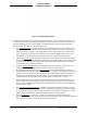
Table Of Contents
- 17001_0_Frt-Matr
- 17001_1_Gen-Info
- 1.1 INTRODUCTION
- 1.2 FUNCTIONAL DESCRIPTION
- 1.2.1 Software Release Summary
- 1.2.2 Transponder Functional Overview
- 1.2.3 GPS Functional Overview
- 1.2.4 Lightning Detection (optional)
- 1.2.5 ADS-B System Overview
- 1.2.6 Traffic Display Functional Overview
- 1.2.7 FISB System Overview
- 1.2.8 Traffic Awareness System (option) Overview
- 1.2.9 ADS-B Traffic Advisory System Overview (optional)
- 1.2.10 Traffic Alert and Collision Avoidance System (option) Overview
- 1.2.11 Terrain Awareness and Warning System Overview (optional)
- 1.2.12 TerrainVisionTM
- 1.2.13 Discrete Inputs and Outputs Functional Overview
- 1.3 EQUIPMENT DESCRIPTIONS
- 1.4 INTERFACES
- 1.4.1 ADS-B Out Fail
- 1.4.2 AHRS Input
- 1.4.3 Altitude Encoder Input
- 1.4.4 Audio Out
- 1.4.5 Standby Mode
- 1.4.6 Audio Mute In and Out
- 1.4.7 Audio Acknowledge
- 1.4.8 RF Suppression Input/output
- 1.4.9 Traffic Alert
- 1.4.10 TAWS Caution and Warning Alert
- 1.4.11 WiFi Interface
- 1.4.12 WOW Input
- 1.4.13 Maintenance Interface
- 1.4.14 GPS Antenna
- 1.4.15 L-Band (978/1030/1090 MHz) Antenna
- 1.4.16 Directional Antenna
- 1.4.17 Traffic Display
- 1.4.18 Weather Display
- 1.4.19 Lightning Detection (WX-500)
- 1.4.20 Control Panel
- 1.5 INSTALLATION CONSIDERATIONS
- 1.6 SPECIFICATIONS
- 1.7 TSO INFORMATION
- 1.8 MODIFICATIONS
- 1.9 SOFTWARE REVISIONS
- 1.10 EQUIPMENT REQUIRED NOT SUPPLIED
- 1.11 EQUIPMENT INTERFACES
- 1.12 OBTAINING SOFTWARE
- 1.13 INSTALLATION PROCEDURE FOR LYNXMSS USB DRIVER
- 1.14 INSTALLATION APPROVAL AND LIMITATIONS
- 17001_2_Instal
- 2.1 INTRODUCTION
- 2.2 UNPACKING AND INSPECTING
- 2.3 INSTALLATION PROCEDURES
- 2.3.1 Panel Mount Location
- 2.3.2 Remote Mount Location
- 2.3.3 Electrical Connections
- 2.3.4 Compatible Equipment Installation Information
- 2.3.5 Discrete Inputs and Output Connections
- 2.3.6 Installation Guidelines for the DCM
- 2.3.7 P1 Mating Connector Assembly
- 2.3.8 Panel mount NGT-9000 Installation
- 2.3.9 Remote Mounted Lynx NGT-9000 Installation
- 2.3.10 CP-2500 Installation Guidelines
- 2.3.11 Antenna Installation Guidelines
- 17001_3_Inst_Check
- 3.1 INTRODUCTION
- 3.2 BASIC OPERATION
- 3.3 MPC (MAT) OPERATION
- 3.4 INSTALLATION PROCEDURE FOR LYNXMSS USB DRIVER
- 3.5 MAINTENANCE MODE
- 3.6 VERIFY SOFTWARE VERSION
- 3.7 SELECT CONFIGURATION OPTIONS
- 3.8 CALIBRATION SETUP
- 3.9 INTERFACE CHECK
- 3.10 SETUP PIM-9000 WIFI MODULE
- 3.11 INSTALLATION CHECKOUT
- 3.11.1 Functional Checks
- 3.11.2 Ground Checks
- 3.11.3 Electromagnetic Interference (E.M.I.) Check
- 3.11.4 Panel mount NGT-9000 Display Check
- 3.11.5 Flight Test
- 3.11.6 Installation Checkout Complete
- 17001_4_Maint
- 17001_5_App-A_signal
- A.1 INTRODUCTION
- A.2 INPUT AND OUTPUT INTERFACES
- A.2.1 Input Power
- A.2.2 RF Suppression Bus
- A.2.3 Audio Output
- A.2.4 Gillham Input (Altitude Input)
- A.2.5 RS-232 Interface
- A.2.6 RS-422 Interface
- A.2.7 ARINC 429 Input
- A.2.8 ARINC 429 Output
- A.2.9 Discrete Input
- A.2.10 Discrete Output
- A.2.11 I2C Serial Bus (Detachable Configuration Module)
- A.2.12 Antenna Connections
- A.3 PIN DEFINITION SUMMARY
- A.4 [J1 CONNECTOR]
- 17001_6_App-B_Environmental
- 17001_7_App-C_Compatibility
- 17001_8_App-D_TSO
- 17001_9_App-E_Questionaire

Lynx NGT-9000
Installation Manual
0040-17001-01 (Revision W) Installation Checkout Page 3-3
3.2.2 Remote Mount Lynx NGT-9000R
The remote version of the Lynx NGT-9000 uses a compatible display and a control panel to view and
initiate commands. An optional cockpit switch and status lamps may be installed to initiate commands or
provide operational status.
• The CP-2500 Control Panel provides all the necessary command and annunciation functions. Refer to
paragraph 3.2.2.2 for operating instructions. Detailed operating instructions for the CP-2500 are
provided in the Pilot Guide for the CP-2500.
The CP-2500 displays GPS INIT, indicating that the GPS is initializing. After 2 minutes, the CP-2500
displays ADS-B SYSTEM FAIL if the GPS position was not acquired. If the CP-2500 displays ADS-
B SYSTEM FAIL in less than 2 minutes, then a different problem has been detected. Cycle power to
the unit. If the problem continues, refer to the troubleshooting section for possible corrective actions.
• The Lynx NGT-9000 can also be interfaced to compatible cockpit displays or a Personal Electronic
Device (PED) used to view traffic and weather. The operation of other third party equipment (i.e.
PED, display, or control panel) is not provided in this manual. Refer to the operations manual for the
third party equipment for command instructions.
3.2.2.1 Power On
There is no power on/off switch for the Lynx NGT-9000. Depending on the aircraft, use either the battery
switches or avionics master switch to apply power.
NOTE
The CP-2500 Control Panel has a power on/off button. Press the small
knob button to apply power to the control panel.
1. Verify the circuit breaker for the Lynx NGT-9000 is closed.
2. Connect aircraft to external power source to conserve aircraft battery power.
3. Apply power to the unit and system components using applicable essential or emergency electrical
buses.
4. Verify power on messages via the CP-2500 or similar messages on other control systems.
5. Normal operation begins within 10 seconds of applying power. During start up, the unit checks for
valid configuration data and initializes self-tests. Refer to the CP-2500 operating instructions in
paragraph 3.2.2.2 for startup messages.
3.2.2.2 CP-2500 Control Panel
The operational information provided in this section is limited. Refer to the CP-2500 Pilot’s Guide or
Installation Manual for details. Refer to the References information in the front section for details.
1. Press the small knob button to apply power to the control panel. To remove power to the unit press
and hold the small knob button until the message "Power Down" is shown on the display.
2. After power is applied, if the self-test passes, the CP-2500 briefly displays "OK". That is followed by
the scrolling of the firmware and hardware levels of the CP-2500 (approximately 15 seconds). The
CP-2500 then reverts to normal operation.
3. The display of the CP-2500 shows the operational mode on the left side of the display and the
squawk code on the right side of the display as shown in Figure 3-2.