
User's Manual


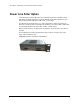
Table Of Contents
- Eclipse Installation Manual for 5.8 GHz Unlicensed Band Rev.003
- Copyright & Terms of Use
- Aviat Networks Support
- Eclipse Product Compliance Notes
- Contents
- Volume I: Introduction and Safety
- Volume II: System Overview
- Volume III: Installation
- Chapter 1. Introduction to Eclipse Installation
- Chapter 2. IRU 600 Installation
- Chapter 3. INU and INUe Installation
- INU/INUe Overview
- Installation Requirements
- Installation Procedure
- Plug-in Installation
- INU/INUe Cable Assemblies
- DAC Trib Connectors and Cables
- NMS Connectors and Cables
- NMS 10/100Base-T Connector
- Maintenance V.24 Connector
- Auxiliary and Alarm Connectors and Cables
- AUX Data Cable: Async, HD26 to Wirewrap, 2 m
- AUX Data Cable: Sync, HD26 to Wirewrap, 2 m
- AUX Data Cable: Async, HD26 to 3 X DB9, 1 m
- AUX Data Cable: Sync, HD26 to 3 X DB9, 1 m
- AUX Data Cable: Async, AUX HD26 to AUX HD26, 1 m
- AUX Data Cable: Sync, AUX HD26 to AUX HD26, 1 m
- AUX Alarm I/O Cable: HD15 to Wirewrap, 2 m or 5 m

ECLIPSE INSTALLATION MANUAL
(Network Equipment-Building System) compliant, the fan air filter must be
installed.
The fan air filter must be inspected regularly and replaced
when dust laden. In normal telecommunicati ons equipment-
room environments inspection must be at not more than 12
monthly intervals. In other environments where air quality is
not control led, more frequent inspecti on i s required.
CAUTION:A heavily dust-laden filter will severely restrict fan air flow
and may lead to over-heating.
Excessive heat is the number one cause of premature equipment
aging and failure.
To maximize long term component reliability, the fan air filter must
not be allowed to become clogged, and ambient temperature limits
must not be exceeded.
Fan Air Filter Installation
For the INUe a fan air filter kit is supplied, comprising a filter frame, filter element,
and fastening screw. For the INU the filter it is a single-piece element.
The filter is installed in the INU/INUe to the right side of the FAN module, as illus-
trated below for an INUe.
Remove the FAN module and slide the air filter into the chassis so that it locates to
the right side of the FAN module backplane connector, and up against the chassis
side. FAN module removal and replacement does not affect traffic.
Installation instructions are included with the fan filter kit.
Figure 3-3. Location of Fan Air Filter in INUe
260-668066-001 OCTOBER 2012 67