
User's Manual


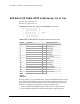


Table Of Contents
- Eclipse Installation Manual for 5.8 GHz Unlicensed Band Rev.003
- Copyright & Terms of Use
- Aviat Networks Support
- Eclipse Product Compliance Notes
- Contents
- Volume I: Introduction and Safety
- Volume II: System Overview
- Volume III: Installation
- Chapter 1. Introduction to Eclipse Installation
- Chapter 2. IRU 600 Installation
- Chapter 3. INU and INUe Installation
- INU/INUe Overview
- Installation Requirements
- Installation Procedure
- Plug-in Installation
- INU/INUe Cable Assemblies
- DAC Trib Connectors and Cables
- NMS Connectors and Cables
- NMS 10/100Base-T Connector
- Maintenance V.24 Connector
- Auxiliary and Alarm Connectors and Cables
- AUX Data Cable: Async, HD26 to Wirewrap, 2 m
- AUX Data Cable: Sync, HD26 to Wirewrap, 2 m
- AUX Data Cable: Async, HD26 to 3 X DB9, 1 m
- AUX Data Cable: Sync, HD26 to 3 X DB9, 1 m
- AUX Data Cable: Async, AUX HD26 to AUX HD26, 1 m
- AUX Data Cable: Sync, AUX HD26 to AUX HD26, 1 m
- AUX Alarm I/O Cable: HD15 to Wirewrap, 2 m or 5 m

VOLUME III, CHAPTER 3, INU AND INUE INSTALLATION
Alarm and Auxiliary cabl es should not terminate to equipment
outside the shelter or building. Use approved sur ge sup-
pr ession equipment when connecting to un-protected external
inputs and outputs.
Refer to:
l
AUX Data Cable: Async, HD26 to Wirewrap, 2m on page 90
l
AUX Data Cable: Sync, HD26 to Wirewrap, 2m on page 91
l
AUX Data Cable: Async, HD26 to 3 X DB9, 1m on page 92
l
AUX Data Cable: Sync, HD26 to 3 X DB9, 1m on page 93
l AUX Data Cable: Async, AUX HD26 to AUX HD26, 1m on page 94
l
AUX Data Cable: Sync, AUX HD26 to AUX HD26, 1m on page 95
l
AUX Alarm I/O Cable: HD15 to Wirewrap, 2m or 5m on page 96
In this section, all connector front views are cable-connector
views.
AUX Data Cable: Async, HD26 to Wirewrap, 2m
Part No: 037-579114-00
Figure 3-17. AUX HD26, 2M, Async, Front View
Table 3-14. Pin Descriptions and Color Code for Part # 037-579114-00
Pin No. Function Wire Color Code
TIA/E1A-562 DCE Direction
1 Output Green/Black
2 Output Black/Green
3 Aux RXD1 Output Black/Orange
4 Output Brown/Black
5 Aux TXD1 Input Orange/Black
6 Input Black/Brown
7 I/O Brown/White
8 I/O White/Brown
9 GND Black/Blue
10 Output White/Gray
11 Output Gray/White
12 Aux RXD2 Output Red/Gray
90 AVIAT NETWORKS