
User's Manual
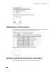


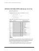


Table Of Contents
- Eclipse Installation Manual for 5.8 GHz Unlicensed Band Rev.003
- Copyright & Terms of Use
- Aviat Networks Support
- Eclipse Product Compliance Notes
- Contents
- Volume I: Introduction and Safety
- Volume II: System Overview
- Volume III: Installation
- Chapter 1. Introduction to Eclipse Installation
- Chapter 2. IRU 600 Installation
- Chapter 3. INU and INUe Installation
- INU/INUe Overview
- Installation Requirements
- Installation Procedure
- Plug-in Installation
- INU/INUe Cable Assemblies
- DAC Trib Connectors and Cables
- NMS Connectors and Cables
- NMS 10/100Base-T Connector
- Maintenance V.24 Connector
- Auxiliary and Alarm Connectors and Cables
- AUX Data Cable: Async, HD26 to Wirewrap, 2 m
- AUX Data Cable: Sync, HD26 to Wirewrap, 2 m
- AUX Data Cable: Async, HD26 to 3 X DB9, 1 m
- AUX Data Cable: Sync, HD26 to 3 X DB9, 1 m
- AUX Data Cable: Async, AUX HD26 to AUX HD26, 1 m
- AUX Data Cable: Sync, AUX HD26 to AUX HD26, 1 m
- AUX Alarm I/O Cable: HD15 to Wirewrap, 2 m or 5 m

ECLIPSE INSTALLATION MANUAL
Pin Function
5 Not used
6 Ethernet receive data -
7 Not used
8 Not used
Figure 3-15. RJ-45 Ethernet NMS Connector(s)
Maintenance V.24 Connector
The V.24 connector provides serial data access for Portal. One industry-standard RJ-
45 to DB-9 V.24 Maintenance Cable is included with every INU.
Table 3-13. RJ-45 V.24 Connector Pin Assignment
Pin Signal
Name
Direction Function
1 DSR/RI In Data Set Ready/Ring Indicator
2 CD In Carrier Detect
3 DTR Out Data Terminal Ready
4 GND System Ground
5 RXD In Receive Data
6 TXD Out Transmit Data
7 CTS In Clear to Send
8 RTS Out Request to Send
Figure 3-16. RJ-45 V.24 Portal Connector (face view)
Auxiliary and Alarm Connectors and Cables
Data is included for AUX Plug-in auxiliary interfaces and cable-sets.
260-668066-001 OCTOBER 2012 89