ECLIPSE TM INSTALLATION MANUAL 5.8 GHZ UNLICENSED BAND Rev.
Eclipse IRU 600 Installation Manual 5.8 GHz Unlicensed Band Manual Rev.
ECLIPSE INSTALLATION MANUAL Copyright & Terms of Use October 2012 This manual is specific to Eclipse with IRU 600 for all-indoor operation on the FCC and Industry Canada 5.8 GHz unlicensed band. Copyright © 2012 by Aviat Networks, Inc. All rights reserved.
ECLIPSE INSTALLATION MANUAL 4. Service Personnel Skill: Service personnel must have received adequate technical training on telecommunications and in particular on the equipment this manual refers to. Trademarks All trademarks are the property of their respective owners. Open Source Software The software included in this product contains copyrighted software that is licensed under the GPL.
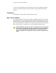
ECLIPSE INSTALLATION MANUAL Aviat Networks Support Service and Technical Support: For customer service and technical support, contact one of the regional Technical Help Desks listed below.
ECLIPSE INSTALLATION MANUAL Eclipse Product Compliance Notes Eclipse has been tested for and meets EMC Directive 2004/108/EC. The equipment was tested using screened cable; if any other type of cable is used, it may violate compliance. Eclipse is a Class A product. In a domestic environment this product may cause radio interference in which case the user may be required to take adequate measures. This equipment is intended to be used exclusively in telecommunications centers. FCC Notices 1. IRU600, 5.
ECLIPSE INSTALLATION MANUAL 3. To ensure compliance with the Industry Canada RF exposure requirements in RSS-102, a minimum distance of 18 meters must be maintained between the antenna and any persons whilst the unit is operational. This calculation is based on the maximum conducted power and maximum antenna gain. 4. IRU600, 5.8GHz, has been certified for use with a parabolic antenna with a maximum gain of 45.9dBi or a flat panel antenna with a maximum gain of 28dBi. 5.
ECLIPSE INSTALLATION MANUAL WEEE Directive In accordance with the WEEE Directive (2002/96/EC), Eclipse is marked with the following symbol: This symbol indicates that this equipment should be collected separately for the purposes of recovery and/or recycling. For information about collection and recycling of Aviat Networks equipment please contact your local Aviat Networks sales office.
ECLIPSE INSTALLATION MANUAL Contents Copyright & Terms of Use Aviat Networks Support Eclipse Product Compliance Notes NEBS Compliance WEEE Directive RoHS Directive Date of Manufacture Contents VOLUME I: INTRODUCTION AND SAFETY About the Documentation Documentation Conventions and Terminology Chapter 1.
ECLIPSE INSTALLATION MANUAL Eclipse IRU 600 IRU 600 Variants 5.8 GHz Unlicensed Band Protection Options Link/Path Protection Interface Protection Network/Data Protection Platform Protection Licensing Capacity Licensing Node Feature Licensing Node Feature Overview Configuration and Management Antennas Power Supply VOLUME III: INSTALLATION Chapter 1. Introduction to Eclipse Installation Installation Overview Installation Tools and Materials Unpacking Chapter 2.
ECLIPSE INSTALLATION MANUAL Installation Requirements Installation Procedure Plug-in Installation INU/INUe Cable Assemblies DAC Trib Connectors and Cables DAC 16xV2 Cable and Connector Data DAC 4x Cable and Connector Data DAC GE3 Ethernet RJ-45 Cables DAC Optical Cable and Connector Data DAC 155eM Cables NMS Connectors and Cables NMS 10/100Base-T Connector Maintenance V.
ECLIPSE INSTALLATION MANUAL Volume I: Introduction and Safety 260-668066-001 OCTOBER 2012 1
VOLUME I, CHAPTER 0, INTRODUCTION AND SAFETY 2 AVIAT NETWORKS
ECLIPSE INSTALLATION MANUAL About the Documentation This Installation documentation provides information on installing an Eclipse Microwave Radio system comprising the INU/INUe and IRU 600. Intended Audience This information is for use by trained technicians or engineers. It does not provide information or instruction on basic technical procedures. Aviat Networks recommends you read the relevant sections of this manual thoroughly before beginning any installation or operational procedures.
VOLUME I, CHAPTER 0, INTRODUCTION AND SAFETY A note i tem i denti fi es addi ti onal i nformati on about a procedure or functi on.
ECLIPSE INSTALLATION MANUAL Chapter 1. Health and Safety This section includes the following health and safety information: l General Health and Safety on page 6 l Operator Health and Safety on page 7 l General Hazards on page 8 l RF Exposure on page 11 l Routine Inspection and Maintenance on page 12 All personnel must comply with the relevant health and safety practices when working on or around Eclipse radio equipment.
VOLUME I, CHAPTER 1, HEALTH AND SAFETY General Health and Safety This table describes general health and safety information about the Eclipse radio. Topic Information Flammability The equipment is designed and constructed to minimize the risk of smoke and fumes during a fire. Hazardous Materials No hazardous materials are used in the construction of the equipment.
ECLIPSE INSTALLATION MANUAL Operator Health and Safety The following table describes the precautions that relate to installing or working on the Eclipse radio. Topic Information Equipment Protrusions The equipment has been designed to be free of unnecessary protrusions or sharp surfaces that may catch or otherwise cause injury during handling. However, always take care when working on or around the equipment.
VOLUME I, CHAPTER 1, HEALTH AND SAFETY General Hazards The following table describes the general hazards that must be addressed when planning and installing an Eclipse system. For more information on health and safety when using Aviat Networks products, refer to the Best Practices Guide. Topic Information Airflow Requirements Rack installations must be made so the airflow required for safe and correct operation of Eclipse is not compromised.
ECLIPSE INSTALLATION MANUAL Topic Information Eclipse Indoor Unit and DC Supply Grounding The ground for Eclipse indoor unit(s) must be connected directly to the dc supply system ground conductor, or to a bonding jumper from a grounding terminal bar, or bus to which the dc supply system grounding is connected. Intrabuilding interfaces and cabling for NEBS compliance Intrabuilding connections to/from Eclipse ports must only be connected via intrabuilding or unexposed wiring or cabling.
VOLUME I, CHAPTER 1, HEALTH AND SAFETY Topic Information Maximum Ambient Temperature The maximum ambient temperature (Tmra) for Eclipse indoor units is +55° C (131° F). Special conditions apply to the INUs - for more information see Power Consumption within Power Supply on page 61. To ensure correct operation and to maximize long term component reliability, ambient temperatures must not be exceeded. Operational specification compliance is not guaranteed for higher ambients.
ECLIPSE INSTALLATION MANUAL RF Exposure To ensure compliance with the FCC RF exposure requirements, a minimum distance of 20 meters must be maintained between the antenna and any persons whilst the unit is operational. This calculation is based on the maximum conducted power and maximum antenna gain. l Eclipse with IRU600, 5.8 GHz, has been tested and certified for use with a parabolic antenna with a maximum gain of 45.9 dBi or a flat panel antenna with a maximum gain of 28 dBi.
VOLUME I, CHAPTER 1, HEALTH AND SAFETY Routine Inspection and Maintenance This section overviews required and recommended inspection and maintenance practices to ensure health and safety of installed equipment is maintained to highest levels. For more information, refer to the Aviat Networks publication: Best Practices.
ECLIPSE INSTALLATION MANUAL Fault Analysis All faults, once cleared, should be the subject of a fault report. The data presented in these reports should be analyzed from time to time to check for any common threads, which may point to a particular weakness in the design, installation, or maintenance of the network or to a specific component.
ECLIPSE INSTALLATION MANUAL Volume II: System Overview 260-668066-001 OCTOBER 2012 15
VOLUME II, CHAPTER 1, SYSTEM DESCRIPTION 16 AVIAT NETWORKS
ECLIPSE INSTALLATION MANUAL Chapter 1. System Overview This section overviews features and capabilities of the Eclipse node (INU/INUe) with companion IRU 600 RF unit for use on the 5.8 GHz unlicensed band. 5.8 GHz operation is compliant with FCC CFR47 Part 15.247, and Industry Canada RSS-210. l It has been tested and certified for use with a parabolic antenna with a maximum gain of 45.9 dBi or a flat panel antenna with a maximum gain of 28 dBi.
VOLUME II, CHAPTER 1, SYSTEM OVERVIEW Aviat Networks is ISO90001:2008 and TL9000 Certified. Full certification means all departments and business units within Aviat Networks have been strictly assessed for compliance to both standards. It testifies that Aviat Networks is a certified supplier of products, services and solutions to the highest ISO and Telecommunication standards available.
ECLIPSE INSTALLATION MANUAL Eclipse Node Eclipse node is available as the 1RU INU, or 2RU INUe. Mandatory plug-ins are the NCC (Node Control Card) and FAN (Fan card). Optional plug-ins include RAC (Radio Access Card), DAC (Digital Access Card), AUX (Auxiliary), NPC (Node Protection Card), and PCC (Power Converter Card). It is designed to operate from a -48 Vdc power supply (+ve earth). For locations where the power supply is +24 Vdc, a plug-in PCC option provides a voltage conversion function.
VOLUME II, CHAPTER 1, SYSTEM OVERVIEW Figure 1-2. INUe See: l Plug-in Cards on page 20 l Data Packet Plane on page 27 l Adaptive Coding and Modulation (ACM) on page 27 l Platforms on page 29 Plug-in Cards Plug-in cards for the INU or INUe enable quick and easy customization on Eclipse configurations. All cards are hot-pluggable. RACs support the radio modem function.
ECLIPSE INSTALLATION MANUAL AUX (Auxiliary card) supports async or sync service-channel connections, and alarm I/O options for connection to external devices. NCC (Node Controller Card) provides Node management and DC-DC converter functions. NCC is a mandatory card. l It manages Node operation and event collection and management. l It incorporates a router function for local and remote network management interconnection. l Node configuration and licensing data is held in flash-memory.
VOLUME II, CHAPTER 1, SYSTEM OVERVIEW ART operation is designed to meet G.8262 synchronization mask requirements for SyncE clock transport. A RAC 60E can link to a RAC 6XE in non-CCDP mode. Figure 1-3. RAC 60E RAC 6XE RAC 6XE adds CCDP operation to 60E capabilities. RAC 6XE additionally supports ART. Two RAC 6XE cards are operated as a CCDP pair, either in the same INU, or in separate co-located INUs to provide double the capacity over one channel, using both the horizontal and vertical polarizations.
ECLIPSE INSTALLATION MANUAL l Advanced options for VLAN tagging, including Q (802.1Q), QinQ (802.1ad), Filtering, Translation l Synchronous Ethernet with Stratum 3 hold-over performance on timing subsystem l RSTP (IEEE 802.1w) l ERP (ITU-T 8032v2) l Ethernet service OAM (IEEE 802.1ag/IYU-T Y.
VOLUME II, CHAPTER 1, SYSTEM OVERVIEW Figure 1-7. DAC 4X DAC 3xDS3 DAC 3xDS3 supports 3xDS3 tributaries on paired mini-BNC connectors. Figure 1-8. DAC 3xE3/DS3 DAC 3xDS3M DAC 3xDS3M supports operational modes of: l Normal DS3 tributary operation (as for DAC 3xDS3) l M13 multiplexer mode. One or two DS3 interfaces are multiplexed to an NxDS1 backplane. l DS3 Ethernet mode to enable up to 43 Mbit/s Ethernet over legacy TDM radio or leased-line links (links must support transparent DS3).
ECLIPSE INSTALLATION MANUAL DAC 2x155o DAC 2x155o supports two OC3 single-mode optical tributaries on SC connectors. Figure 1-12. DAC 2x155o DAC 155oM DAC 155oM multiplexes an OC3 optical tributary to an NxDS1 backplane. The user interface is provided on an SFP optical transceiver. Different SFPs support 1310nm single-mode, or 850nm multi-mode. It functions as a terminal multiplexer; it terminates or originates the OC3 frame.
VOLUME II, CHAPTER 1, SYSTEM OVERVIEW Figure 1-15. NCC The NCC is a mandatory plug-in for an INU/INUe. It performs key node management and control functions, and provides various dc rails from the -48 Vdc input. It also incorporates a plug-in flash card, which holds Node configuration and license data. Power input limits are -40.5 to -60 Vdc. The power connector is a D-Sub M/F 2W2. The +ve dc return pin is connected to chassis ground. Figure 1-16. NCC FAN The FAN is a mandatory plug-in.
ECLIPSE INSTALLATION MANUAL INU -48Vdc input. -56 Vdc represents the typical float voltage for a battery-backed 48 Vdc supply. Figure 1-19. PCC Data Packet Plane The high-performance data packet plane (DPP) operates independently of the backplane. The DPP is enabled via direct cable connection between the front panel packet data port on a RAC 60E, RAC 6XE, and a front-panel port on a DAC GE3. Customer traffic connected to the DACs is bridged to the RACs, and then to the RF transceiver; the IRU 600.
VOLUME II, CHAPTER 1, SYSTEM OVERVIEW Note that while adaptive modulation can also be used on PDH links and combined PDH and Ethernet links, unlike Ethernet there is no QoS synergy on PDH connections. Ethernet connections enjoy real synergy through the QoS awareness on the DAC GE3 GigE switch, and the service provisioning provided by any MPLS or PBB-TE network overlay. All high priority traffic, such as voice and video, continues to get through when path conditions are poor.
ECLIPSE INSTALLATION MANUAL Platforms Eclipse supports flexible customization of traffic type, traffic capacity, and traffic protection for up to three links using the INU, and to six links using the INUe. Platform Layout Platform INU Supports 3 non-protected links or 1 protected/diversity and 1 non-protected link. 1RU. INUe Supports up to 6 non-protected links for: 1 protected/diversity and 4 non-protected links, or 2 protected/diversity and 2 non-protected links, or 3 protected/diversity links. 2RU.
VOLUME II, CHAPTER 1, SYSTEM OVERVIEW Slots INUe - Slots 1, 2, 3, 4, 5, 6 are universal: any RAC, DAC, or AUX plug-in - Slots 7, 8, 9 are restricted: any DAC, or AUX, except DAC 155oM/eM and AUX where NMS access is required1 - Slot 10 is restricted: NPC option only - NCC and FAN slots are dedicated - the INUe is supplied standard with a single 2RU FAN, though accepts two 1RU FANs - RAC/RAC, or RAC/DAC 155oM/eM protected pairings must be installed in the positions indicated by the arrows - For protected DA
ECLIPSE INSTALLATION MANUAL Eclipse IRU 600 The IRU 600 is a rack-mounted transceiver unit for co-location with an INU/INUe as an all-indoor installation. l IRU 600 is 1+1 optimized. It comprises one or two RFUs (radio frequency units), and a filter-based ACU (antenna coupler unit). o The ACU design supports paired and unpaired Tx/Rx frequency splits and incorporates an optional expansion port to allow other radio links onto its waveguide feed for co-path operation.
VOLUME II, CHAPTER 1, SYSTEM OVERVIEW l Average recovery times of 50 ms compared to times approaching 200 ms for the Tx-mute/unmute operation of the coupler-based IRU 600(v1) solution. o Times apply to full MHSB operation (standby Tx on), and muted standby Tx mode (standby Tx on Tx mute). The standby Tx is terminated into a dummy load via the Tx switch. MHSB mode increases power consumption as both transmitters are fully active both online and offline Tx status is captured in real time.
ECLIPSE INSTALLATION MANUAL l l o The V3 RFU (with conversion kit installed) can be used in non-protected and HSB V1 and V2 chassis. o V1 or V2 RFUs cannot be installed in a V3 chassis. V1 and V2 ACUs are interchangeable. The V3 ACU is not. o A V1 ACU can be installed in a V2 chassis, and vice-versa. o V1 and V2 ACUs cannot be installed in a V3 chassis. Similarly a V3 ACU cannot be installed in a V1 or V2 chassis. All IRUs are fully over-air compatible with like-for-like configurations.
VOLUME II, CHAPTER 1, SYSTEM OVERVIEW Operational Limitations and Restrictions Unlicensed band operation means sharing the air-space with other operators of unlicensed band links. Interference is possible. l IRU 600 5.8 GHz operation is 'narrow-band'; it competes/shares spectrum with other narrow-band links and with spread-spectrum links. l Performance could deteriorate over time with the introduction of other links in the same geographical area.
ECLIPSE INSTALLATION MANUAL Protection Options Eclipse supports link, interface, network, and platform protection options: Link/Path Protection Hot-standby, space diversity, frequency diversity, or dual protection options are available. RACs and their companion IRU 600 are protectable. Rx voting is hitless/errorless; Tx switching is not hitless. The maximum restoration time for a Tx switch is 200 ms. A remote Tx switch is forced in the event of a silent Tx failure.
VOLUME II, CHAPTER 1, SYSTEM OVERVIEW Network/Data Protection l Ethernet ring network protection is supported on DAC GE3 using ERP (ITU-T 8032v2 Ethernet Ring Protection) or RSTP (IEEE 802.1w). l Ethernet data redundancy is supported on L1 and L2 link-aggregated links (DAC GE3). l PDH ring protection is supported by an DS1 loopswitch capability, or a ringwrap Super PDH (SPDH) option.
ECLIPSE INSTALLATION MANUAL Power Supply Protection l Protection is hitless for an NCC power supply failure. If the NCC converter or one of its supply rails fails, the NPC will take over without interruption. And vice versa. l With an NPC installed, the NCC can be withdrawn and replaced without further impacting traffic. l For 24 Vdc operation two PCCs are required for platform protection, one each for the NCC and NPC.
VOLUME II, CHAPTER 1, SYSTEM OVERVIEW Licensing Eclipse is subject to capacity and feature licensing. Capacity Licensing Capacity licensing is INU and INUe based (node-based). A single license applies across all installed RACs installed in an INU/INUe. l Licensed capacity ranges from 50 Mbps with license EZE-08001, to 2 Gbps with license EZE-08010 l Capacity license is auto-allocated or user-allocated between installed RACs.
ECLIPSE INSTALLATION MANUAL EZF-03: Secure Management (NMS) Secure Management applies to Eclipse NMS access over the network, and to local access via the Portal craft tool. l Provides secure management access to Eclipse over an unsecured network. l Protects Eclipse configurations from accidental or intentional modification by unauthorized personnel. l Keeps track of all events for accountability. l Based on FIPS 140-2 validated algorithms.
VOLUME II, CHAPTER 1, SYSTEM OVERVIEW 40 l EZF-61 EZG-61 IRU 600 High power option 1 x RFU l EZF-62 EZG-62 IRU 600 Nodal High power option 2 x RFU l EZF-63 EZG-63 IRU 600 Nodal High power option 3 x RFU l EZF-64 EZG-64 IRU 600 Nodal High power option 4 x RFU l EZF-65 EZG-65 IRU 600 Nodal High power option 5 x RFU l EZF-66 EZG-66 IRU 600 Nodal High power option 6 x RFU AVIAT NETWORKS
ECLIPSE INSTALLATION MANUAL Configuration and Management Eclipse is a software-driven product; there are no manual controls. Configuration and management is achieved via Portal and ProVision. Portal is a PC based configuration and diagnostics tool for Eclipse. ProVision is the Eclipse network element manager. ProVision also supports other Aviat Networks products, including legacy products.
VOLUME II, CHAPTER 1, SYSTEM OVERVIEW Antennas Antennas for the 5.8 GHz unlicensed band must be FCC approved. l Parabolic antennas must have a maximum gain not exceeding 45.9 dBi. l Flat panel antennas must have a maximum gain not exceeding 28 dBi. For information on antenna types and availability, contact Aviat Networks or your supplier. Antenna mounts are designed for use on industry-standard 115 mm OD (4.5 inch) pipe-mounts.
ECLIPSE INSTALLATION MANUAL Power Supply Eclipse is designed to operate from a -48 Vdc power supply (+ve earth) but will operate to specification over a voltage range of -40.5 to -60 Vdc. A plug-in PCC option provides a voltage conversion function for locations where the power supply is +24 Vdc. It converts +24 (19 to 36) Vdc to -56 Vdc for connection to the INU -48Vdc input. -56 Vdc represents the typical float voltage for a batterybacked -48 Vdc supply.
ECLIPSE INSTALLATION MANUAL Volume III: Installation 260-668066-001 OCTOBER 2012 45
VOLUME III, CHAPTER 1, INSTALLATION 46 AVIAT NETWORKS
ECLIPSE INSTALLATION MANUAL Chapter 1. Introduction to Eclipse Installation This section provides a list of recommended installation tools and materials, and a procedure for unpacking and checking the equipment. Ecl i pse has been tested for and meets EMC Di recti ve 89/336/EEC. The equi pment was tested usi ng screened cabl e; i f any other type of cabl e i s used, i t may vi ol ate compl i ance. CAUTION: Eclipse is a Class A product.
VOLUME III, CHAPTER 1, INTRODUCTION TO ECLIPSE INSTALLATION F or more i nformati on on i nstal l ati on practi ce refer to the Avi at Networks' publ i cati on ' Best Practi ces Gui de' . Installation Tools and Materials Ensure you have the following tools and material before going to site. These are items to be sourced/supplied by the installer. The items are indicative for standard installations. For non-standard installations additional materials and tools may be required. Table 1-1.
ECLIPSE INSTALLATION MANUAL Chapter 2. IRU 600 Installation Bef or e commi ssi oni ng an IRU 600 and compani on INU, i ts antenna, wav egui de, and wav egui de pr essur i zati on equi pment must be i nstal l ed accor di ng to manuf actur er ’s i nstr ucti ons. For an overview of IRU 600 features and function, see Eclipse IRU 600 on page 31. For information on installing an INU, see INU and INUe Installation on page 59.
VOLUME III, CHAPTER 2, IRU 600 INSTALLATION IRU 600 Installation Procedure This procedure applies to IRU 600(v1), IRU 600v2, and IRU 600v3. Unless otherwise stated, reference to IRU 600 refers to all IRU 600 variants. 1. Fit the rack mounting brackets onto the chassis. o Brackets can be mounted in either a forward mount or a flush mount position. o Brackets can be mounted such that the grounding stud is to the left or right side. 2. Install the chassis.
ECLIPSE INSTALLATION MANUAL Figure 2-2. Example Cabling Diagram on Rear of ACU Front Panel 5. 6. For the IRU 600v2 and IRU 600v3 with Tx coaxial switch, fit the RFU-toswitch cable assembly. o The fixing post in front of the RFU connectors can be removed to aid connector access. See step 3 above. o Ensure cables connect to the correct RFU. Refer to the cabling diagram on the rear side of the ACU front cover.
VOLUME III, CHAPTER 2, IRU 600 INSTALLATION Figure 2-4. IRU 600v2 Tx Switch and RFUv2 Connections Figure 2-5. IRU 600v3 Tx Switch and RFUv3 Connections CAUTION:Ambient temperatures must not exceed 55 0C (131 0F). If installed in a rack cabinet, it is the ambient within the cabinet. Grounding The chassis grounding stud accommodates ground cables up to 16 mm2 (AWG 6). The stud also provides jack plug connection for a wrist strap. 52 1.
ECLIPSE INSTALLATION MANUAL Safety Requirements for Equipment Grounding l Do not assume that an existing rack or mounting frame is correctly grounded. Always check the integrity of the ground connections, which must include a check through to the master ground for the station, which should be located at the point of cable entry to the equipment building. Ground wires must provide a direct, low impedance path to the master ground bar.
VOLUME III, CHAPTER 2, IRU 600 INSTALLATION ground-bar end. Torque the grounding post screw to 1.2-1.5 Nm (10-13 in-lbs). l All bare conductors must be coated with an appropriate antioxidant compound before crimp connectors are fitted. l All unplated connectors, braided strap, and bus bars must be brought to a bright finish and then coated with an antioxidant before they are connected.
ECLIPSE INSTALLATION MANUAL l The high power RFU provides a wide-mouth connection for +/- 21 to 60 Vdc. Both +ve and -ve pins are isolated from ground. l The integral DC/DC converter provides polarity protection, under/over voltage shutdown, over-current limit, and thermal shutdown. l For operation from +24 Vdc supplies, the associated INU/INUe must be fitted with a PCC to convert +24 Vdc to -48 Vdc.
VOLUME III, CHAPTER 2, IRU 600 INSTALLATION Expansion Port Use The expansion port allows system expansion through the addition of co-located IRU 600 radios, or external radio equipment. When multiple carriers are deployed on a common branching network (same antenna), the selection and installation of branching network components must be such that threshold degradation caused by intermodulation products is avoided.
ECLIPSE INSTALLATION MANUAL Figure 2-6. IRU 600v3 Fan Removal Next Step l 260-668066-001 INU/INUe installation. Refer to INU and INUe Installation on page 59.
ECLIPSE INSTALLATION MANUAL Chapter 3. INU and INUe Installation The INU and the INUe are the indoor units for the Eclipse Node. This chapter includes: l INU/INUe Overview on page 60 l Installation Requirements on page 69 l Installation Procedure on page 71 l Plug-in Installation on page 74 l INU/INUe Cable Assemblies on page 77 CAUTION:Do not turn power off within 10 minutes of initial INU/INUe turn-on, or initial turn-on after a new compact flash card is installed.
VOLUME III, CHAPTER 3, INU AND INUE INSTALLATION INU/INUe Overview The INU/INUe is a rack-mounted unit that pairs with one or more RFUs. An INU/INUe comprises a chassis and plug-ins. Dedicated slots are provided for the NCC and FAN plug-ins, and either four slots (INU) or ten slots (INUe) for optional RAC, DAC, AUX and NPC plug-ins.
ECLIPSE INSTALLATION MANUAL Power Supply The dc power suppl y must be UL or I EC compl i ant for SELV (Safety Extra Low Vol tage) output (60 Vdc maxi mum l i mi ted). INUs require a -48 Vdc power supply (+ve earth), but will operate to specification over a voltage range of -40.5 to -60 Vdc. The return (+ve) pin on the NCC and NPC power supply connectors is clamped to chassis ground via polarity-protecting power FETs.
VOLUME III, CHAPTER 3, INU AND INUE INSTALLATION Power consumption figures are for a -48 Vdc supply voltage at normal room ambients. Table 3-1. Typical Plug-in Power Consumptions Item Consumption RAC 60E 12W RAC 6XE 17W DAC 16xV2, 4x, 3xE3/DS3, 3xE3/DS3M 2.5W DAC 155o, 2x155o, 2x155e, 155oM, 155eM 4W DAC GE3 13W NCC 11W NPC 8W AUX 1W FAN 1RU 2W FAN 2RU 2W The tables below list nominal figures for an IRU 600.
ECLIPSE INSTALLATION MANUAL l For both standard power and high power operation DC power to the RFU(s) is provided from its INU/INUe via the RAC - RFU cable. Table 3-3. Nominal IRU 600v3 Power Consumption for QPSK at Max Tx Power Configuration 5.8/L6 GHz Typical 5.
VOLUME III, CHAPTER 3, INU AND INUE INSTALLATION INUe Loading Rules for Operation up to 55ºC (131ºF) The following loading rules must be followed when dimensioning the total power consumption of an INUe that is required to operate in ambient temperatures up to 55ºC (131ºF): l If the total power consumption of all cards installed exceeds 85 watts, an NPC must be fitted, a 2RU FAN card must be fitted, and 5.04 or later SW loaded. l With this configuration confirmed (NPC + 2RU FAN + 5.
ECLIPSE INSTALLATION MANUAL El evated ambi ent temperatures shoul d be avoi ded. The ambi ent temperature i s the ai r temperature i n the i mmedi ate operati ng envi ronment of the chassi s, whi ch i f i nstal l ed i n a rack, i s the ambi ent appl yi ng to i ts l ocati on wi thi n the rack. CAUTION:The ambient temperature maximums must not be exceeded. Over-temperature operation is a primary factor affecting long term component reliability.
VOLUME III, CHAPTER 3, INU AND INUE INSTALLATION Power Cables The INU power cable is supplied in the IDC Installation Kit. It is supplied with a Dsub M/F 2W2 connector fitted at one end and wire at the other. The cable is nominally 5 m (16 ft), and the wires are 4 mm2 (AWG 12). The cable is used for -48 Vdc connections to an NCC or NPC, or for +24 Vdc connections to a PCC. The blue wire must be connected to live (-48 Vdc or +24 Vdc); the black wire to ground (+48 Vdc or -24 Vdc). Figure 3-2.
ECLIPSE INSTALLATION MANUAL (Network Equipment-Building System) compliant, the fan air filter must be installed. The fan ai r fi l ter must be i nspected regul arl y and repl aced when dust l aden. I n normal tel ecommuni cati ons equi pmentroom envi ronments i nspecti on must be at not more than 12 monthl y i nterval s. I n other envi ronments where ai r qual i ty i s not control l ed, more frequent i nspecti on i s requi red.
VOLUME III, CHAPTER 3, INU AND INUE INSTALLATION Power Line Filter Option An external DC power line filter option is available and must be installed with an INU/INUe for NEBS compliance. It ensures Eclipse meets EMI requirements specified within Telcordia GR-1089-CORE, Issue 4, June 2006. It is IRU tall and 140mm wide (5.
ECLIPSE INSTALLATION MANUAL Installation Requirements This table lists typical INU Installation requirements. Function/Requirement Details Restricted access The INU/INUe and its associated dc power supply must be installed in a restricted access area such as a secure equipment room, closet, or cabinet. For NEBS compliance, this equates to installation of the INU/INUe in a secure, restricted access central office (CO) or customer premises (CP) location. Required Rack Space The INU requires 44.
VOLUME III, CHAPTER 3, INU AND INUE INSTALLATION Function/Requirement Details Power Supply +24 Vdc A PCC is required to provide a +24 Vdc to -48 VDC conversion. The dc power supply supplying the PCC must be -ve grounded. There must be no switching or disconnecting devices in the ground conductor between the dc power supply and the point of connection to a PCC.
ECLIPSE INSTALLATION MANUAL Installation Procedure 1. Fit the rack mounting brackets to the chassis with the grounding stud to left or right side for the most direct ground wire path to the rack ground bar. 2. Locate the INU/INUe in the equipment rack and secure it using four No.12 Phillips dome-head screws from the IDC installation kit. 3.
VOLUME III, CHAPTER 3, INU AND INUE INSTALLATION connected. This does not apply to tinned, solder-plated, or silver-plated connectors and other plated connection surfaces – but all must be clean and free of contaminants. o 5. All raceway fittings must be tightened to provide a permanent lowimpedance path. Install the plug-ins in their assigned slot positions, and check that their front panels are flush-fitted (not protruding) and held secure by their fasteners.
ECLIPSE INSTALLATION MANUAL CAUTION: This product meets the global product safety requirements for SELV (safety extra low voltage) rated equipment and the input voltage must be guaranteed to remain within the SELV limits (60 V maximum) in the event of a single internal fault. Always check the integrity of the dc power supply to an INU/INUe right to its source. Never assume that the supply provided to the pickup point in a rack is correct.
VOLUME III, CHAPTER 3, INU AND INUE INSTALLATION Plug-in Installation Installing or changing out a plug-in is a straightforward process. l The table below lists plug-in requirements at installation or subsequent upgrade. l Unless specified by the customer, plug-ins will not be installed in an INU/INUe at shipment. Instead, each is individually packed within the shipping box. For a description of the plug-ins, see Plug-in Cards on page 20.
ECLIPSE INSTALLATION MANUAL Function/Requirement Priority Details Finger-grip fasteners Plug-ins must be withdrawn and inserted using their fingergrip fasteners/pulls. Never withdraw or insert using attached cables, as damage to the plug-in connector and its PCB attachment can occur. If not complied with, the Aviat Networks warranty may be voided. Hot-swappable Plug-ins are hot-swappable. - Removal of an in-service payload plug-in will interrupt its traffic.
VOLUME III, CHAPTER 3, INU AND INUE INSTALLATION Function/Requirement Priority Details DACs DAC combinations DACs can be fitted singly or in combination to provide a mix of interface types and capacities provided they have a common backplane configuration. The backplane can be set for: - 1.5 Mbit/s / DS1 - 3 Mbit/s / DS3 - 155 Mbit/s / OC3 Mux version DACs allow a mix of interfaces from a common DS1 backplane configuration.
ECLIPSE INSTALLATION MANUAL INU/INUe Cable Assemblies CAUTION:Eclipse tributary, auxiliary and NMS cables are not to be routed with any AC mains power lines. They are also to be kept away from any power lines which cross them. For safety reasons tributary, auxiliary and NMS cables should not be connected to outside plant. Use approved surge suppression equipment when connecting to unprotected external inputs and outputs.
VOLUME III, CHAPTER 3, INU AND INUE INSTALLATION Each cable supports up to 8 tribs. Two cables are required per DAC if more than 8xE1/DS1 tribs are to be connected. Figure 3-5. DAC 16xV2 Free End Trib Cable RX indicates data into the DAC 16xV2 (DAC Rx). TX indicates data out from the DAC 16xV2 (DAC Tx). DAC 16xV2 HDR-E50 To BNC Cable Assembly The HDR to BNC 75 ohm cable is available in lengths of 2.3 m or 5.3 m. Each cable supports up to 8 tribs.
ECLIPSE INSTALLATION MANUAL Figure 3-6. DAC 16xV2 BNC Trib Cable Assembly Figure 3-7. DAC 16xV2 BNC Trib Cable Connections Arrow towards BNC indicates data out (DAC Tx). Arrow away from BNC indicates data in (DAC Rx). The 1/9 in the label indicates that it is for trib 1 if the cable assembly is used with the trib 1-8 connector, or trib 9 if used with the trib 9-16 connector. This also applies for 2/10, 3/11, etc. up to 8/16.
VOLUME III, CHAPTER 3, INU AND INUE INSTALLATION Each cable supports up to 8 tribs. Two cables are required per DAC if more than 8xE1/DS1 tribs are to be connected. Figure 3-8. DAC 16xV2 RJ-45 Trib Cable Figure 3-9. DAC 16xV2 RJ-45 Trib Cable Connections DAC 16xV2 HDR-E50 To Free End Y-Cable Assembly This cable is for use with DAC 16xV2 1+1 protected operation. It is available in lengths of 3.5 m, 15.5m or 5 m. Impedance is nominally 120 ohms.
ECLIPSE INSTALLATION MANUAL Each cable supports up to 8 tribs. Two cables are required per DAC if more than 8xE1/DS1 tribs are to be connected. Figure 3-10. DAC 16xV2 Free End Y-Cable RX indicates data into the DAC 16xV2 (DAC Rx). TX indicates data out from the DAC 16xV2 (DAC Tx). DAC 16xV2 HDR-E50 To BNC Y-Cable Assembly This cable is for use with DAC 16xV2 1+1 protected operation. It is available in lengths of 3.5 m, 15.5m or 5 m. Impedance is nominally 75 ohms. Each cable supports up to 8 tribs.
VOLUME III, CHAPTER 3, INU AND INUE INSTALLATION Figure 3-11. DAC 16xV2 Trib BNC Y-Cable Figure 3-12. DAC 16xV2 Trib BNC Y-Cable Connections Arrow towards BNC indicates data out (DAC Tx). Arrow away from BNC indicates data in (DAC Rx). The 1/9 in the label indicates that it is for trib 1 if the cable assembly is used with the trib 1-8 connector, or trib 9 if used with the trib 9-16 connector. This also applies for 2/10, 3/11, etc. up to 8/16.
ECLIPSE INSTALLATION MANUAL DAC 4x Cable and Connector Data Refer to: l DAC 4x BNC Cable Assembly on page 83 l DAC 4x RJ-45 to RJ-45 Straight Cable on page 83 l DAC 4x RJ-45 to RJ-45 Crossover Cable on page 84 l DAC 4x RJ-45 to Wire Wrap Cable Assembly on page 84 l DAC 4x RJ-45 Connector Pin Assignments on page 85 DAC 4x BNC Cable Assembly The assembly is provided as a kit of three cables. Each kit provides: l One RJ-45 to 2 x BNC female, 0.5m long.
VOLUME III, CHAPTER 3, INU AND INUE INSTALLATION For Connection Function, receive specifies data in to the DAC; transmit is data out from the DAC. Table 3-6.
ECLIPSE INSTALLATION MANUAL Each cable supports one trib. Four cables are required if all four ports of the DAC 4x are to be connected. Receive specifies data in to the DAC; Transmit is data out from the DAC. Table 3-8.
VOLUME III, CHAPTER 3, INU AND INUE INSTALLATION Table 3-10. RJ-45 Ethernet Cable Options Description Part Number Ethernet Cable, RJ45 to RJ45, 2 m 037-579124-001 Ethernet Cable, RJ45 to RJ45, 5 m 037-579125-001 Ethernet Cable, RJ45 to RJ45, 15 m 037-579126-001 The cables are industry-standard straight (Mdi) Ethernet RJ-45 to RJ-45.
ECLIPSE INSTALLATION MANUAL ATTENUATOR 3M, SC, 10DB SC Single 1310 nM DAC 1/2x155o 037-579209-001 ATTENUATOR 5M, SC, 10DB SC Single 1310 nM DAC 1/2x155o 037-579210-001 SIMPLEX 3M MM LC TO LC LC Multi 850 nM DAC 155oM 037-579431-001 SIMPLEX 10M MM LC TO LC Multi 850 nM DAC 155oM 037-579432-001 SIMPLEX 5M MM LC TO LC, SC SC Multi 850 nM DAC 155oM 037-579434-001 SIMPLEX 3M MM LC TO LC, FC FC Multi 850 nM DAC 155oM 037-579440-001 SPLITTER 2M MM SC TO LC/LC Multi 850 nM DAC 155oM 037-
VOLUME III, CHAPTER 3, INU AND INUE INSTALLATION Multi-mode, part no. 037-579390-001: Y-cable, multi-mode, LC to SC, 2m (6 ft) splitter/combiner l Other cabl e opti ons are avai l abl e for LC connecti on to F C or ST. Contact Avi at Networks or your suppl i er for detai l s. DAC 155eM Cables The following cables are for use with the DAC 155eM (electrical SFP): Part number Description 037-579462-003 CABLE, M1.0/2.3 TO M1.6/5.6, 75 OHM STRANDED 3m 037-579462-005 CABLE, M1.0/2.3 TO M1.6/5.
ECLIPSE INSTALLATION MANUAL Pin Function 5 Not used 6 Ethernet receive data - 7 Not used 8 Not used Figure 3-15. RJ-45 Ethernet NMS Connector(s) Maintenance V.24 Connector The V.24 connector provides serial data access for Portal. One industry-standard RJ45 to DB-9 V.24 Maintenance Cable is included with every INU. Table 3-13. RJ-45 V.
VOLUME III, CHAPTER 3, INU AND INUE INSTALLATION Al arm and Auxi l i ary cabl es shoul d not termi nate to equi pment outsi de the shel ter or bui l di ng. Use approved surge suppressi on equi pment when connecti ng to un-protected external i nputs and outputs.
ECLIPSE INSTALLATION MANUAL Pin No.
VOLUME III, CHAPTER 3, INU AND INUE INSTALLATION Pin No.
ECLIPSE INSTALLATION MANUAL Table 3-16. Pin Descriptions and Color Code for Part # 037-579116-00 AUX Function AUX 1 AUX 2 AUX 3 Pin No. TIA/E1A562 DCE Direction Pin No. Pin No. Pin No. 3 5 AuxRXD1 Output 2 AuxTXD1 Input 3 9 GND 12 AuxRXD2 Output 14 AuxTXD2 Input 18 GND (Shared) 21 AuxRXD3 Output 2 23 AuxTXD3 Input 3 5 2 3 5 5 AUX Data Cable: Sync, HD26 to 3 X DB9, 1 m Part No: 037-579117-001 Figure 3-20. AUX HD26 to 3 X DB9, 1m, Sync, Front Views Table 3-17.
VOLUME III, CHAPTER 3, INU AND INUE INSTALLATION AUX Function 11 2AuxRXC- Output AUX 1 AUX 2 6 12 2RXD- Output 2 13 2RXD+ Output 7 14 2TXD+ Input 3 15 2TXD- Input 8 16 2AuxTXC+ I/O 4 17 2AUXTXC- I/O 9 18 GND (Shared) 19 3AuxRXC+ Output 1 20 3AuxRXC- Output 6 21 3RXD- Output 2 22 3RXD+ Output 7 23 3TXD+ Input 3 24 3TXD- Input 8 25 3AuxTXC+ I/O 4 26 3AUXTXC- I/O 9 5 AUX 3 5 AUX Data Cable: Async, AUX HD26 to AUX HD26, 1 m Part No: 037-579120
ECLIPSE INSTALLATION MANUAL AUX Data Cable: Sync, AUX HD26 to AUX HD26, 1 m Part No: 037-579121-001 Figure 3-22. AUX TO AUX, HD26, 1m, Sync, Front View Table 3-19.
VOLUME III, CHAPTER 3, INU AND INUE INSTALLATION AUX Alarm I/O Cable: HD15 to Wirewrap, 2 m or 5 m Part No: 037-579112-001, 2 m Part No: 037-579113-001, 5 m Figure 3-23. ALARM I/O, HD15, 2M, WIREWRAP, Front View Table 3-20. Pin Descriptions for 037-579112-001 and 037-579113-001 Pin No.
260-668066-001 WWW.AVIATNETWORKS.