User's Manual

MDR2400-SR, MDR5800-SR and Orion 5825-SR
Issue 10 Page 43
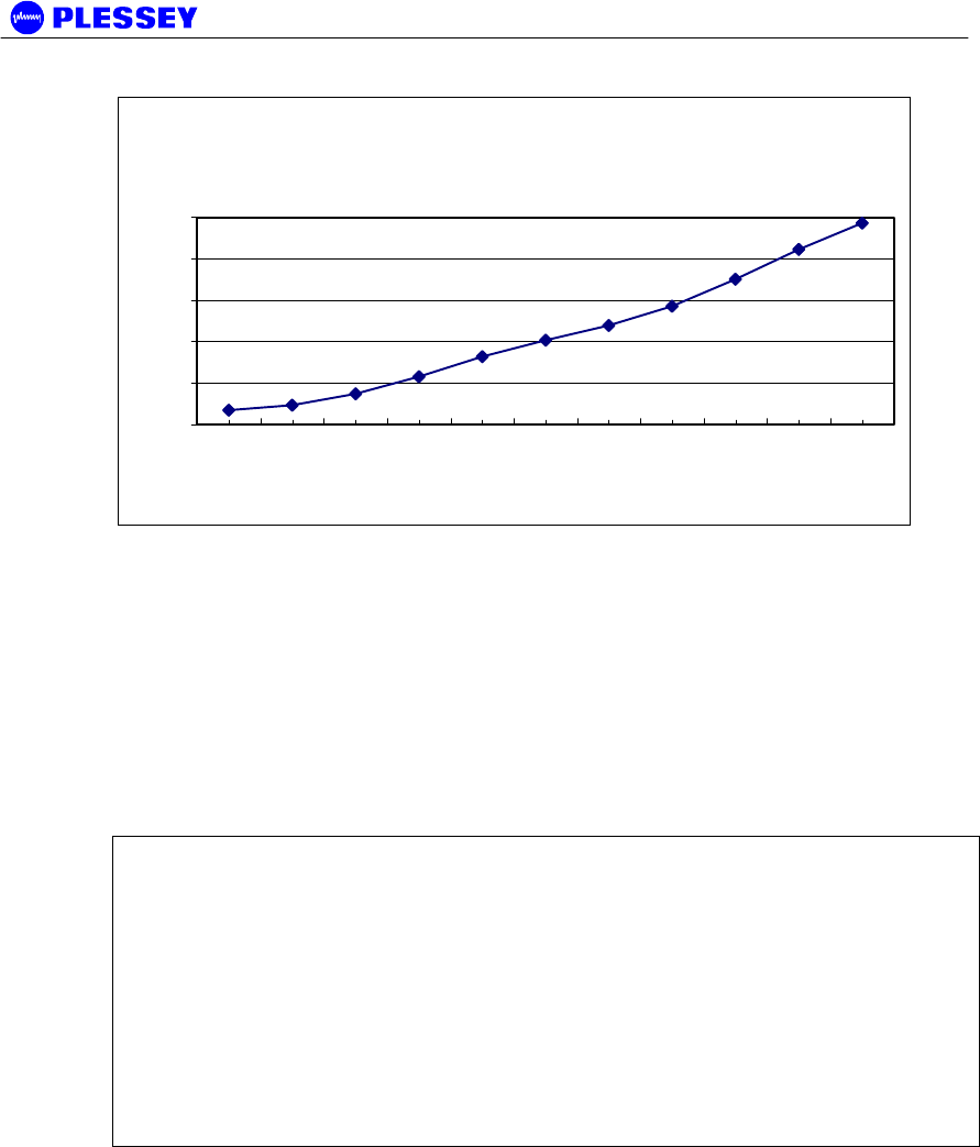
Typical Version 2 MDR OU RSSI Voltage vs Received
Signal Power (5.8GHz)
0.4
0.6
0.8
1
1.2
1.4
-80 -75 -70 -65 -60 -55 -50 -45 -40 -35 -30
Received Signal Power [dBm]
Outdoor Unit RSSI
Voltage
Figure 7. Typical Version 2 MDR5800 OU RSSI Voltage as a function of RF input
power level
-80 dBm Average 0.436 ± 0.029 V : MIB RSSI 95 ± 1 dBm (see comment below)
-30 dBm Average 1.333 ± 0.047 V : MIB RSSI 54 ± 2 dBm (see comment below)
The front panel RF Link LED, the Received Signal Strength Indicators (RSSI : on
NMS, via SNMP or as an Electrical signal on the Outdoor Unit), Carrier-detect (NMS,
SNMP) and Frame Lock (NMS, SNMP) indicators are available to assist with link
installation and alignment.
NOTE 1 The MIB lists a value representative of the received signal level in [-dBm].
This value corresponds to the signal power measured in a 200 kHz BW centred at the
receive frequency of the radio.
When not in spectrum analyser mode, the Orion OU translates the measured signal
power to a value corresponding to the wanted signal power in the receiver bandwidth.
NOTE 2 For the MDR OU, the RSSI values displayed in the MIB are representative of
the signal level measured over a 200kHz BW. Add ~20dB to the MIB value for a
wanted spread spectrum signal. The NMS / GUI will do this adjustment automatically
and will therefore always display the correct RSSI value.
NOTE 3 Due to the technique used to calculate the RSSI level of a wanted signal, the
measured RSSI level can differ from the actual value with up to ±3 dB.


