User's Manual

MDR2400-SR, MDR5800-SR and Orion 5825-SR
Issue 10 Page 36
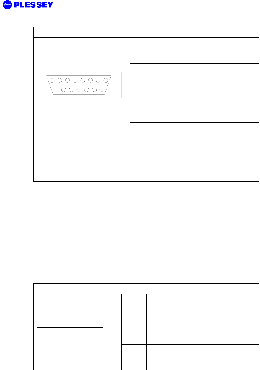
Table 11. Auxiliary In/Out Connector Pin Outs
Indoor unit connector Pin
No
Signal
1
OUTPUT 1 COMMON
2
OUTPUT 1 NORMALLY-OPEN
3
OUTPUT 1 NORMALLY-OPEN
4
OUTPUT 1 NORMALLY-CLOSED
5
OUTPUT 1 NORMALLY-CLOSED
6
OUTPUT 1 COMMON
7
OUTPUT 2 COMMON
8
OUTPUT 2 COMMON
9
OUTPUT 2 NORMALLY-OPEN
10
OUTPUT 2 NORMALLY-OPEN
11
OUTPUT 2 NORMALLY-CLOSED
12
INPUT 1
13
INPUT 1 RETURN
14
INPUT 2
15-pin D-type female
1
8
9
15
15
INPUT 2 RETURN
4.2.8 Connecting the Service (Wayside) Serial Channel (Optional)
This ‘clear’ serial channel can transport up to 115,200 bps across the radio link. This
channel does not interfere with the payload data channels. The port is configured as
DCE.
1. Connect the serial data interface cable to the Service channel connector on the
Indoor Unit rear panel. The supplied serial data cable can be used to connect to
this port after the software setup is completed.
2. See the table below for Indoor Unit connector pin assignments when a custom
cable needs to be assembled.
3. Secure the connector using locking screws.
Service Channel Connector Pinouts
Indoor Unit connector Pin
No
Signal
2
TD
3
RD
4
DTR
5
GROUND
6
DSR
7
RTS
9-pin D-type Female
Connector
8
CTS
4.2.9 Connecting the Element Manager Port
The Element Manager port is used to connect the Indoor Unit to a PC/Laptop serial
port. This enables the Indoor Unit to be configured using the supplied NMS / GUI


