User's Manual

MDR2400-SR, MDR5800-SR and Orion 5825-SR
Issue 10 Page 35
4.2.5 Balanced Payload Data : RJ48
1. Assemble the T1 / E1 payload data input and output cable. See the table below
for Indoor Unit connector pin assignments.
2. Connect the payload data cables to the RJ48 connectors (numbered 1-8 for tribs
1-8) on the front panel of the Indoor Unit.
Standard termination of this port is 110 Ohms. On the Orion 25, 75 Ohms termination
is available on request (please contact the factory).
It is recommended to use a cable that connects to pin 1,2,4, and 5 only since the other
pins on the RJ48 are not used to transfer data.
NOTE Rx implies IN (signal expected to go INTO the interface), Tx implies OUT
(signal coming out of the interface)
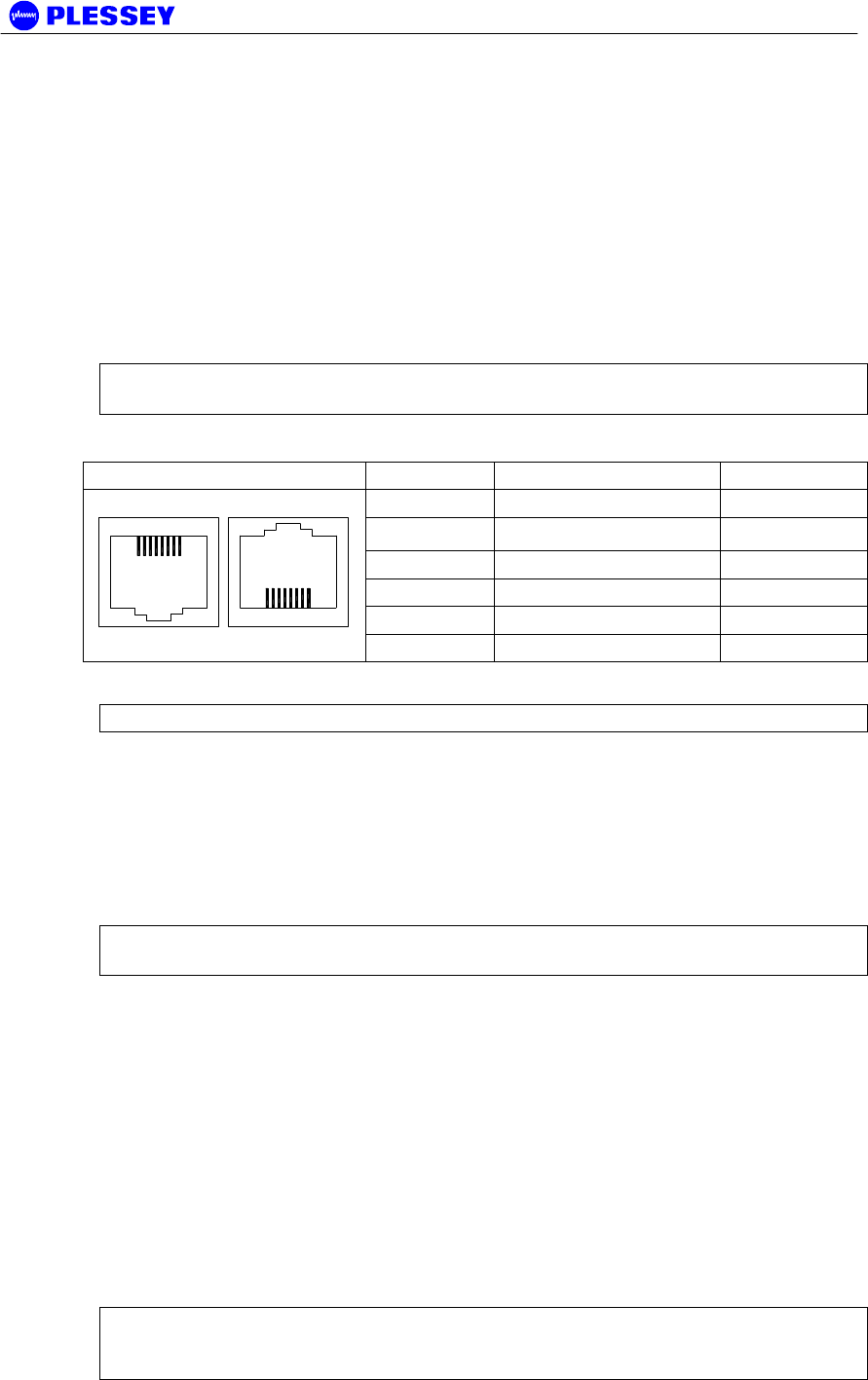
RJ48C Socket Pin Description Direction
1 R (Ring 1) TX
2
T (Tip 1)
TX
3,6 50 Ohm terminated N/A
4 R1 (Ring) RX
5 T1 (Tip) RX
1 8
1 8
7,8 No Connection N/A
NOTE Use Twisted Pair Cable conductors for pins: 1 & 2, 3 & 6 and 4 & 5.
4.2.6 Unbalanced Payload Data : BNC
One of the variants of the MDR Indoor Unit has a set of 75 Ohm BNC’s on the front
panel as well as the DB25 connector.
• Rx implies IN (signal expected to go INTO the interface)
• Tx implies OUT (signal coming OUT of the interface)
NOTE Tribs are numbered 0-3 on the front panel, but are called 1-4/1-8 in the NMS /
GUI.
4.2.7 Connecting Auxiliary In/Out (Optional)
The auxiliary in/out port is used to:
ff. Monitor switch-closure events using two isolated inputs.
gg. Control line connections using normally-open and normally-closed relay outputs.
Connect the port:
1. Assemble an auxiliary in/out cable using a 15 way D-type male connector
according to connector pin assignments shown in Table 11.
2. Connect to the cable Indoor Unit auxiliary in/out connector.
3. Secure the connector using locking screws.
NOTE The Orion and MDR Indoor Units are equipped with only two relays. The
Normally-Open and Normally-Closed output for each of the two relays are however
provided on the Auxiliary Connector for convenience.


