® AVerMedia AVerDiGi EB1304NET SATA + EB1304NET SATA User Manual Nov.
FCC NOTICE (Class A) This device complies with Part 15 of the FCC Rules. Operation is subject to the following two conditions: (1) this device may not cause harmful interference, and (2) this device must accept any interference received, including interference that may cause undesired operation. .Federal Communications Commission Statement NOTE- This equipment has been tested and found to comply with the limits for a Class A digital device, pursuant to Part 15 of the FCC Rules.
WARNING TO REDUCE RISK OF FIRE OR ELECTRIC SHOCK, DO NOT EXPOSE THIS APPLIANCE TO RAIN OR MOISTURE CAUTION IF THERE IS ANY DAMAGE, SHORTAGE OR INAPPROPRIATE ITEM IN THE PACKAGE, PLEASE CONTACT WITH YOUR LOCAL DEALER. WARRANTY VOID FOR ANY UNAUTHORIZED PRODUCT MODIFICATION NOTICE - INFORMATION IN THIS DOCUMENT IS SUBJECT TO CHANGE WITHOUT NOTICE. - THE INFORMATION CONTAINED HEREIN IS TO BE CONSIDERED FOR REFERENCT ONLY.
Table of Contents Chapter 1 Introduction................................................................................ 1 1.1 Package Content .................................................................................................. 1 1.2 Features and Specifications ................................................................................. 1 1.3 Front Panel ........................................................................................................... 3 1.3.1 EB1304NET SATA .....
.2 To Backup Recorded Video File ......................................................................... 36 Chapter 6 ImageVerification ..................................................................... 37 6.1 To Run the ImageVerification.............................................................................. 37 Chapter 7 iEnhance................................................................................... 38 7.1 To Use iStable .........................................................
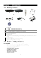
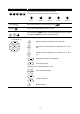
Chapter 1 1.1 Introduction Package Content AVe rDiG AVerM ed ® i EB 130 ia Quic 4NE k In TS stalla ATA tion Guid e B A (1) (2) (4) (3) (5) (6) (7) (1) DVR Unit A: AVerDiGi EB1304NET SATA unit B: AVerDiGi EB1304NET SATA+ unit i The model of DVR unit is depending on your purchase. (2) Remote Control (batteries included) (3) Quick Installation Guide (4) Power Cord * The power cord varies depending on the standard power outlet of the country where it is sold.
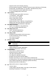
Supports UPnP (Universal plug and play) Remote Software Integration: CM3000, Remote Console, WebViewer, PDAViewer, HandyViewer, and SmartViewer ( for Symbian / Windows Smart phone) - Non-PC stand-alone network digital video recorder - On Screen Display(OSD) control menu Video Feature - 4 composite video inputs (BNC connector) - 1 Composite & 1 VGA outputs - Video compression: MPEG4 - Video Format: NTSC and PAL - 1 channel audio input/output - Display resolution:720 x 480/720 x 576 (NTSC/PAL) - Display frame
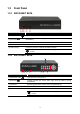
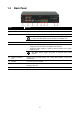
1.3 Front Panel 1.3.1 EB1304NET SATA Name Function (1) DVR Power LED Light when the unit is power on (2) HDD LED Indicate the hard disk running state. Light when the HDD is running (Read/Write) (3) IR Sensor Receive signal from the remote control to operate the unit (4) IR Sensor Port To connect extended IR sensor cable (5) USB 2.0 Port Connect to pen drive / external hard disk for backup i If the external hard disk is first time using, please format to FAT32 format. 1.3.
Name (6) 1/2/3/4/Quad Function Use these buttons in playback mode to switch to display each channel in full screen or view all channels at the same time Use the buttons in setting password of OSD menu to: For ”1” (7) Record REC (8) Menu (9) UP/DOWN/SELECT (10) Playback/OSD Menu Control Buttons For “2” For “3” For “4” For “0” Start video recording.
1.
1.5 Setting Up the DVR Unit 1.5.1 Installing the Hard Disk The DVR unit allows user to install one SATA hard disk. i For hard disk spec, please referring to http://www.avermedia.com/AVerDiGi/ → Products → Embedded Analog DVR → AVerDiGi EB1304NET SATA series → Hardware Recommendations The “compatible hard disks” indicated in the above recommendation list only means that these commercially available hard disks were tested with AVerMedia products and functioned well under normal operation conditions.
5. Secure the hard disk inside the unit then replace 6. unit cover Push the cover forward and secure the cover 7. You may now connect all the cables. When the power is connected, the Power LED light turns on 1.5.2 Adjust Fan Speed The DVR provides 3 speed of fan for user to adjust by actual condition. 1. Loosen all screws 2. Push the cover backward and lift 3. Move the pin cover to the pin. 3x is maximum, 2x 4. Push the cover forward and secure the cover is medium and 1x is low.
1.5.3 Connecting Devices The back panel of the DVR unit, user can connect up to 4 video cameras, 4 sensor devices, 1 alarm device and output video to a TV or CRT/LCD monitor. Connecting the unit to a pen drive or external hard disk through USB interface for backup, then use the bundled software enables user to transfer, playback and segment the video.
1.5.4 Connecting the Sensor device/Relay device /PTZ Camera The Audio, Sensor, Alarm, and RS485 port enable you to connect 1 audio input device, 1 audio output, 4 sensor inputs, 1 relay outputs, and PTZ camera. Just connect the external audio input/output device, sensor, relay, and PTZ camera pin directly to the pinhole. Check the table below and locate which pinhole is assigned to sensor input and relay output. The signal from the sensor (i.e.
1.5.4.3 RS-485 Pin Definition When connect PTZ camera through RS485 interface, please refer to the following pin definition to connect the DVR and PTZ. Pin # i DVR site PTZ site 15 TX+ RS485 TX+ signal RS485 RX+ signal 16 TX- RS485 TX- signal RS485 RX- signal 17 RX+ RS485 RX+ signal RS485 TX+ signal 18 RX- RS485 RX- signal RS485 TX- signal If user uses the 2 wires for the PTZ camera connection, please connect to the RS-485 TX+ and TX- of the DVR site.
Chapter 2 2.1 Operating the DVR unit Familiarizing the Buttons of Remote Control Use the Remote control to operate the OSD menu on surveillance screen.
USB backup(see 2.1.2) Button Function ▼ (14) To move the selection to the left and right ▼ (15) ▲ To go up and down and select the items in the menu list or change the settings ▼ (16) To enter the OSD Main menu / Exit from the main menu or sub-menu display ZOOM+ To zoom in view of PTZ camera (17) ZOOM- To zoom out view of PTZ camera (18) PTZ camera control button. Press PTZ button( 1 + camera channel 4 )can enter PTZ mode to control PTZ camera.(see 2.1.
A-B again to set the B point of video segment. On the surveillance screen will display “A-B” and repeat playing the AB point video segment which user has set. To cancel AB repeat, press A-B again. 2.1.2 Using USB Backup Button User can press button to backup the AB Repeat video file. 1. Set the AB Repeat file (see 2.1.1). USB BAKCUP YES (SELECT) / NO(ME NU ) 2. Plug in pen drive or external hard disk to DVR system. 3. During the AB Repeat playback, press 4. And then, press button.
2.1.3.2 To Set Preset Position User can set 9 preset positions for PTZ camera. Using 1 to 9 button to set the preset position. 1. Press and camera channel number button ( 1 PTZ 2 3 4 ) to enter PTZ ▼ ▼ mode. 2. Using ▲ , ▼ , and to adjust the PTZ camera to the position that user wants. 3. Press any number button over 3 seconds and the position will be saved. 4. To move the PTZ camera to preset position, just press the number button. 2.1.3.
HARD DISKS INFORMATION VERSION S3 . 01. 01. 00. 03 HDD CHECKING . . . MASTER HDD SIZE 76GB 509MB HDD FORMAT YES (SELECT) / NO (MENU) 2.2.1 Set up the System Date and Time Before starting record video, adjust the date and time first. 1. Press to call up the OSD menu and then use ▲ or and select Submenu. And then, press ▲ and ▼ to go up and down to confirm the selection. 2. In Submenu, use ▲ and ▼ to go up and down and select the Time Setup and press again to make a selection.
1 CH1: Camera1 3 CH2: Camera 2 7 CH3: Camera 3 16 9 CH4: Camera 4 5 QUAD: 4-Channel
2.4 Playback the Video 1. Press 2. Use the ▼ The DVR system can record and playback video simultaneously. Therefore, user don’t need to stop recording while playback the video. and ▲ SEARCH METHOD TIME SEARCH EVENT LIST buttons to go up and down and ▼ select TIME SEARCH or EVENT LIST. Then, press to make a selection. ▼ or TIME SEARCH (search by date and time): Use the and ▲ buttons and select SEARCH ▼ TIME. Then press or ▼ 1. TIME SEARCH HARD DISK : again to make the selection. 2.
Chapter 3 OSD Navigation Tree The follow figure is an OSD menu tree map. To call out the OSD menu, press remote control.
3.1 Menu Function If the unit is currently recording the video, user may have to stop video recording to change the settings. Use remote control to navigate in the OSD menu. The red frame turns yellow when you are making a selection.
OSD MENU S C HE DUL E : 00 AL W A Y S : 00 AL W A Y S : 00 AL W A Y S : 00 AL W A Y S : 00 AL W A Y S : 00 AL W A Y S : 00 AL W A Y S : 00 AL W A Y S : 00 AL W A Y S : 00 AL W A Y S : 00 AL W A Y S : 00 AL W A Y S : 00 AL W A Y S REC REC REC REC REC REC REC REC REC REC REC REC REC S UB ME NU P AS S WOR D C HANG E V IDE O A DJ US T ME NT TIME SETUP ON AUT O R E C OR D AUT O S C AN NO P AS S WOR D S E T UP ON AUDIO R E C OR D AUDIO MUT E OF F V IDE O S Y S T E M NT S C OF F MUT IP L E R E MOT E 1 R E MOTE I
OSD MENU Description S UB ME NU P AS S WOR D C HANG E V IDE O A DJ US T ME NT TIME SETUP ON AUT O R E C OR D AUT O S C AN NO P AS S WOR D S E T UP ON AUDIO R E C OR D AUDIO MUT E OF F V IDE O S Y S T E M NT S C OF F MUT IP L E R E MOT E 1 R E MOTE ID PTZ SETUP CHANNEL NAME SETTING USER(NETWORK) The login account for remote connection through the internet. User account only can view and playback recorded video by Web viewer (ex: Internet Explorer), but no authority to change the DVR system’s setting.
OSD MENU TIME SETUP DATE TIME AUTO SYNC TIME TIME ZONE LAST SYNC TIME Description 2007 / 03 / 12 15 : 45 : 57 OFF GMT 2007 / 03 / 12 12 : 00 : 00 DELETE RECORDED FILES OLDER THAN 0 DAYS Set a period of time to delete recorded files that save on hard disk. DAYLIGHT SAVING DELETE RECORDED FILES OLDER THAN 10 DAYS DAYLIGHT SAVING DAYLIGHT SAVING START END TIME OFFSET OFF 2008 / 01 /01 00 : 00 2008 / 06 /30 00 : 00 00 : 00 DAYLIGHT SAVING To enable/disable daylight saving function.
OSD MENU Description S UB ME NU P AS S WOR D C HANG E V IDE O A DJ US T ME NT TIME SETUP AUT O R E C OR D ON AUT O S C AN P AS S WOR D S E T UP NO AUDIO R E C OR D ON AUDIO MUT E OF F V IDE O S Y S T E M NT S C OF F MUT IP L E R E MOT E 1 R E MOTE ID PTZ SETUP CHANNEL NAME SETTING S3. 01. 01. 00. 03 AUDIO MUTE Enable/disable to hear audio sound. To hear sound, make sure the unit is connected to an audio output device (ex: speaker).
OSD MENU PTZ SETUP CAMERA PTZ CONTROL PTZ ID PROTOCOL BAUD RATE AUTO PAN DWELL TIME Description 1 OFF 000 PELCO-D 2400 1-1 05 SEC PROTOCOL Select the protocol of PTZ camera. The protocol will be differenced that depends on the brand of PTZ camera. The DVR system currently supports 2 protocols ─ PELCO-D and PELCO-P. Please refer to your PTZ camera user manual to make sure which protocol is using for. BAUD RATE To setup the baud rate of PTZ camera.
OSD MENU HARD DRIVE SETUP OVERWRITE ENABLED HDD SIZE HDD USED HDD FORMAT Description YES 1560,12MB 250MB OVERWRITE ENABLED 1% Enable/disable overwriting the earliest record when the hard disk space runs out. By default, the HDD overwrite setting is enabled HDD FORMAT For security purpose, you may have to enter the password to format hard disk To format hard disk: ▲ and ▼ buttons to go up and down and select HDD FORMAT. Then press or 2. In the CHECK PASSWORD screen, press or ▼ 1. Use the ▼ .
OSD MENU SENSOR SETUP SENSOR REC TIME ALARM OUT TIME CHANNEL - 1 CHANNEL - 2 CHANNEL - 3 CHANNEL - 4 VIDEO LOSS ALARM Description 010 010 NOT NOT NOT NOT 1 SENSOR REC TIME Set the amount of time (in second) to start record when the sensor has triggered SEC SEC INSTALLED INSTALLED INSTALLED INSTALLED 2 3 ALARM OUT TIME Set the amount of time (in second) to continue sending the alarm once triggered 4 CHANNEL 1~4 Customize the initial state of the attached sensor.
OSD MENU - SUBNET: It is a bitmask used to identify the sub network DHCP 1 2 0080 5005 3 4 - - and how many bits provide room for host addresses. Enter the subnet mask of the IP address which user has assigned to DVR system. GATEWAY: A network device act as a passageway to internet. Enter the network gateway IP address DNS: Domain Name Server translates domain names (such as www.abb.com.tw) to IP addresses. Enter the IP address of DNS if it is available. MAC ADDRESS: Only for user information.
PPPOE: Point-to-Point Protocol over Ethernet is a network protocol for encapsulating PPP frames in Ethernet frames. It is used mainly with ADSL services. If your network is using ADSL service connecting to internet, and then, select PPPOE mode. Use ▲ and ▼ buttons to go up and 4 ▼ down and select PPPOE, and then press or to make selection. A message window will show up as below: G E T IP N O W ! W A IT IN G . . .
Description NETWORK SETUP IP MODE NW ENABLE VIDEO PORT UPGARDE PORT STATIC 1 2 0080 5005 3 4 UPGRADE PORT A port for the remote update DVR system firmware. Any port can be assigned as an upgrade port, except the ports are already used by the network services. The default upgrade port is 5005. For Upgrading DVR firmware, please contact your local dealer. Please DO NOT cut off the power of the DVR system while the firmware is upgrading. Power failure will cause the permanent damage of the DVR system.
Chapter 4 4.1 Using the USB Playback Console Recommended system requirements Pentium®4 2.4GHZ or above Windows®2000/ XP/Vista DDR 256 MB Graphic function must support DirectDraw Audio card or built-in Speaker 1 available USB2.0 port 4.2 Installing the USB Playback Console To install the USB Playback Console: 1. Place Installation CD into the CD-ROM drive. When the installation main screen appears, click Install USB Playback Console and then follow the on screen instructions 2.
4.3 Running the USB Playback Console To run the application, click the Name (1) Exit icon on the PC desktop Function Exit/ Minimize the application or chose Cancel to go back to the application. About: shows DVR application version information. (2) Progress bar Show the progress of the file being played. You may move the bar to seek at any location of the track. (3) Split Screen Mode Select from different screen view to playback the recorded video file of the entire camera or one camera on screen.
Name (5) Open File Function To select the video file for playing. The playback application supports *.dvr and *.avf file type. - DVR Recorded File (HD): To playback the recorded video from the hard disk which was recording video on the DVR system. (see aslo Chapter 4.3.2) - Backup File(.dvr): The file is backup and save in *.dvr file format. (see also Chapter 4.3.3) - Backup File(.avf): The file is backup and save in *.avf file format. The recorded video backup to pen drive is in *.avf (see also 4.3.
4.3.1 To Cut and Save the Portion of the Recorded Video 1. Use the Playback Control buttons or drag the bar on the playback progress bar and pause on where you want to start the cut. Then, click Segment to set the begin mark. 2. Use the Playback Control buttons or drag the bar on the playback progress bar and pause on where you want to end the cut. Then, click Segment to set the end mark. To cancel segmentation, click Segment button again. 3. 4. Click Output button to save the wanted portion.
4.3.3 Playback Backup File(*.dvr) - Click Open File button. - Select Backup File(*.dvr) and click OK. - Locate the backup file folder and click OK. i - When open the backup video file, just locate the where backup file folder is. And then, Playback Date/Time Selection window appears. Select the date and time and click OK. 4.3.4 Playback Backup File (*.avf) To playback backup file in *.
Chapter 5 Backup Recorded Video File HDD Backup application provides user an interface to view recorded video from hard disk. 5.1 Familiarizing with HDD Backup Application (3) (1) (4) (5) (6) (7) (2) (8) (9) (10) (11) (12) (14) Name (13) Function (1) Date Select the date for events (2) Hour and Channel User can select the hour and channel for events. : All events in this hour and channel have been selected.
Name (8) Progress bar Show the progress of the event being played. User may move the bar to seek at any location of the track (9) Source Disk To select the hard disk drive (10) (11) (12) (13) (14) Target Path Event (%) Total (%) Stop Start To locate on where user wants to save the file Display the backup progress rate of event in percentage Display the total backup progress rate in percentage Stop backup progress Start backup progress 5.2 1. 2. 3. 4.
Chapter 6 ImageVerification Image Verification is a watermark-checking program to identify the authenticity of a saved image (e.g. by snapshot). This program can only verify uncompressed bmp image files. 6.1 1. 2. 3. 4. To Run the ImageVerification To run the ImageVerification application, click the Watermark button on USB Playback Application main interface. In the ImageVerification screen, click Load Source Image and locate the image source. Click Verify Image to begin the process.
Chapter 7 iEnhance The bundled iEnhance is a video editing tool and can only be used with *.dvr video file. It allows you to adjust the video picture quality, segment and save the selected portion of the video, zoom in and out the image, and print or save the screen shot. You can also save the setting and apply it on other files. To run iEnhance application, click iEnhance button on USB Playback Console interface.
Name Function (13) Sharpness Improve the overall image by enhancing edges. This gives the image more depth. (14) Effects Gray Scale: convert the image into black and white (monochrome). Normalize: adjust the brightness intensity. Equalize: automatically adjust the images that are too dark. De-interlace: smooth out the overlying frames. Static: de-interlace for motionless scene. Dynamic: de-interlace for moving scene.
Chapter 8 Using the Remote Programs User can use Microsoft Internet Explorer to access DVR system by entering the IP address. To use this feature, make sure that you PC and EB 1304 NET both are connected to the internet and the Network feature is enabled. Accessing this feature for the first time you will be prompted by your browser to install WebCamX.cab, allow the installation and you should be able to connect and login afterwards.
8.1 Familiarizing the Web Viewer Buttons Right-clicking on the Web Viewer video screen, enables you to start video recording, change video quality, switch camera and enable/disable DirectDraw. (10) (9) (8) (7) (6) (1) Name (3) (4) (5) Function (1) DirectDraw i (2) Enhance the video quality. Not all graphic cards can support this function. If you can not see the screen display correctly or screen is messed, please check with VGA card vendor.
Name (10) Select cameras to view Function Select to the view camera from different server. In Select Camera dialog box, Display column, click to enable/disable viewing the camera. Click Add Server and select the server type between DVR and IP Cam to add. Click Delete Server to delete the selected item. Click Import to load the previous saved list. Click Export to save the list. Click Apply All to change all the camera video quality based on the selected setting. Click OK to exit.
8.1.1 To Setup Remote System Setting Click OK to exit and save the setting and Cancel to exit without saving the setting. The setting here applies to Remote DVR only. i After changed the DVR system setting, refresh your web browser in order to apply the new setting to the DVR system. 8.1.1.1 System Setup (1) (2) (3) (1) Audio mute Enable/disable to hear audio sound of local DVR. To hear sound, make sure the unit is connected to an audio output device (ex: speaker).
(3) DLS Setup daylight saving settings. - Enable DLS To enable/disable daylight saving function. - START Setup daylight start up date and time. - END Setup daylight stop date and time. - TIME OFFSET Assign a time that it is for daylight saving time offset in your time zone. For example: if the time zone is in U.S. Eastern, the time offset is 1 hour. 8.1.1.
8.1.1.3 Record Setup (1) (2) (3) (4) (5) (6) (7) (8) (1) Record Select Enable/disable the channel number to record video i The channels which could be recorded should be enabled in the CAMERA SELECT first. (2) Record Mode Select D1/CIF recording mode. Under D1 mode, the video recording is in full screen resolution. Each channel is recorded at a maximum frame rate of 15fps. You can switch to view the video in single full screen or 4 split screen.
is applicable in Always Record mode under schedule setting. (6) Audio Record Enable/disable audio recording. To record sound, make sure the microphone is connected to the unit (7) Disk Overwrite Enable Enable/disable replacing the earliest record when the hard disk space runs out. By default, the HDD overwrite setting is enabled (8) Motion Detection - Motion Camera Enable/disable the channel number to detect motion.
8.1.1.4 Alarm/Sensor Setup (1) (2) (3) (1) Sensor Setup - Sensor Status Customize the initial state of the attached sensor for every camera. Refer to the table below to customize the sensor state. Not installed: Indicates that there is no sensor connected Normal open: Indicates that the initial state of the sensor is normal open. Video recording initiate when there is a changes in the sensor state Normal close: Indicates that the initial state of the sensor is normal close.
motion. i The Motion Detection must be enabled first, the alarm sending mail will send out the mail when detect motion. - Sensor Alarm: Issue an alarm when sensor of selected channel has triggered. - Video Loss: Issue an alarm when t selected channel’s video is lost.
8.1.1.5 Network Setup (1) (2) (3) (1) IP Mode - Static IP Assign a fixed and global IP address for the DVR system. Fill in the columns of Static IP section. IP: Assign a constant IP address which real IP addresses give from ISP. Mask: Enter the subnet mask of the IP address which user has assigned to DVR system. i It is a bitmask used to tell how many bits in an octet(s) identify the subnetwork, and how many bits provide room for host addresses.
- UPNP Enable: Enable/disable UPnP function that can automatically configure the port setting to the local router. UPNP Port: Assign a port for UPNP service using. (3) DDNS DDNS (Dynamic Domain Name Service) is a data query service mainly used on the Internet for translating domain names into Internet addresses. Users can register their own domain name on http://ddns.avers.com.tw. (See Appendix A) - Domain Name Enter the domain name that user has registered.
8.1.1.6 Password Change Click Remote setup button on Web Viewer main interface, and then, click User button to call out the Password Change interface. (1) (2) (1) Superuser Change the remote accessing password of super user. Superuser has the authority to remote setup the DVR system configuration on Web Viewer.
8.2 Familiarizing the Remote Console Buttons (12) (11) (10) (9) (13) (8) (1)(2) (3) Name (4) (5) (6) (7) Function (1) Exit Close the Remote Console. (2) Audio button Enable/disable the sound. (3) Split Screen Mode Select from 2 different split screen type to playback the recorded video file of all the camera, or one camera over the other or alongside on a single screen. i - If there are only 4 cameras, you won’t be able to switch to 9, 16, and 13 split screen mode.
To Setup Remote Console Setting Click Setup button to call out the System Setting windows. Click OK to exit and save the setting and Cancel to exit without saving the setting. (1) (1) (1) (1) (1) Storage Path Set the directory on where to save the data. When there is not enough free space to record one hour data, the system automatically replaces the oldest data. In case you have more than one storage path, the system automatically saves the data to the next storage path.
8.3 Using the Remote Playback To use this feature, first you need to select the source of the file. Click the Playback button. And then, in the Select Playback Mode dialog box, choose Local Playback to open the file that is recorded in the Remote Console, and Remote Playback to open the file that is recorded in the DVR server. When you choose Remote Playback, select Download and Playback. Click OK to proceed and Cancel to void this operation.
You can only select one block when you choose Download and Playback. 3. Click OK to proceed and Cancel to void this operation. 4. If you select Download Playback and after making the selection, the system divides the selected hour into 16 video thumbnails. In the Time Selection screen, click on the video thumbnail you want to download (see also Chapter 8.3.2). 8.3.
Name Function (5) Playback Control Buttons Begin: Move at the beginning of the recorded video file. Previous: Go back to the previous frame. Slower: Play the recorded video file at the speed of ½x, ¼x, or ⅛x. Rewind: Wind back the video file. Pause: Briefly stop playing the recorded video file. Play: Play the recorded video file. Faster: Play the recorded video file at the speed of 2x, 4x, or 8x. Next: Go to the next frame. End: Go to the end of the video file.
8.3.2 Familiarizing the Download and Playback Buttons (8) (7) (6) (5) (4) (1) (2) Name (1) Exit (2) Progress bar (3) Playback Control Buttons (4) Status bar (5) Export (6) Segment (7) Full screen (8) Visual Search (3) Function Close the application Show the progress of the file being played. You may move the bar to seek at any location of the track. Begin: Move at the beginning of the recorded video file. Previous: Go back to the previous frame.
8.3.2.1 To Cut and Save the Wanted Portion of the Recorded Video 1. Use the Playback Control buttons or drag the bar on the playback progress bar and pause on where you want to start the cut. Then, click Segment to set the begin mark. 2. Use the Playback Control buttons or drag the bar on the playback progress bar and pause on where you want to end the cut. Then, click Segment to set the end mark. To cancel segmentation or set the segment marks from the start, click Segment button again. 3. 4.
8.3.2.3 To Search Using the Intelligent Search 1. Click on the video screen on where you want to search. 2. Click Intelligent Search. The Intelligent Search text (red) would appear at the lower left corner of the screen. Intelligent Search 3. When the Intelligent Search Setting dialog box and motion detector frame appear, you may adjust the sensitivity bar and the motion detector frame size and location. To set motion detector frame size and location, left click and drag on the screen.
Chapter 9 Using HandyViewer to Access DVR server Users can use a mobile phone to access the DVR through Internet. Make sure your mobile phone support IE browser and is connected to the internet. To access the DVR server, open IE browser and enter http://enter server IP or domain name here/mobile. You can see the latest screen shot. Click << >> to change the channel or camera and Refresh to reload new screen shot. 9.
5. When done, click OK. 9.1.2 To install PDAViewer from the Internet Make sure you are connected to the internet. 1. Open the web browser and enter the server IP. Then click the hyperlink Download PDA-Viewer. 2. When the Download dialog box appears, enable Open file after download and click Yes. After the installation, the PDAViewer icon will appear in the Programs list.
9.1.3 To Use the PDAViewer 1. Run the PDAViewer in the Programs. 2. Familiarizing the PDAViewer buttons. Name (1) Connect (2) (1) (3) (4) (5) (10) (9) (8) (6) (7) Function Hook up to the DVR server. Make sure you are connected to internet. When the iView screen appears, click Add to add DVR server. Enter the server IP, port, user ID, password and select the connection type. Then, click OK.
3. To change the video quality, enable/disable audio, and select to display different camera, tap on the video screen longer the pop up menu will appear. 9.1.4 To Playback in PDA Viewer 1. 2. 3. 4. 5. 6. Run the PDA-Viewer in the Programs. Hook up to the DVR server. Click Connect icon and select the DVR server Click Playback to enter playback option screen Select the camera, data, and time Click Playback to start playing the recorded video 7.
11. User can change the relay status. Select the relay and tap on video screen longer the pop up menu will appear, and then, select the status (ON, OFF, Trigger) 9.2 Using JavaViewer to Access DVR Server Using the mobile phone within Symbian Smart Phone OS to access the DVR through Internet. Make sure your mobile phone supports Symbian Smart Phone OS and can be connected to the internet.
9.2.1 To Use the JAVAViewer 1. Run the JAVAViewer program. 2. Enter the DVR IP address, port number, user ID, and password. Please refer to your DVR server setting for that information. 3. And then, select the Connect to connect to DVR server. 4. Click Yes to accept the data from DVR server. 5. When connection is success, you will see the camera video on the screen. 6. To switch to different camera view, select menu and select the channel. 7.
Appendix A Registering Domain Name DDNS (Dynamic Domain Name Service) is a data query service mainly used on the Internet for translating domain names into Internet addresses. It allows remote clients to intelligently search dynamic servers without any previous enquiring for servers’ Internet addresses. In order to take advantage of this intelligent service, first register your domain name on the following Web site http://ddns.avers.com.tw 1. User Login - Browse the website ddns.avers.com.
Appendix B Network Service Port The following table shows the ports that DVR server uses for certain network service.
Warranty Notice LIMITED WARRANTY AVerMedia TECHNOLOGIES, Inc.