4X4 HDMI Matrix Switch with 3D over CAT-5 with IR Pass-Through Model #: SW-HDM3D-C5-4X4 © 2011 Avenview Inc. All rights reserved. The contents of this document are provided in connection with Avenview Inc. (“Avenview”) products. Avenview makes no representations or warranties with respect to the accuracy or completeness of the contents of this publication and reserves the right to make changes to specifications and product descriptions at any time without notice.
including, but not limited to, the implied warranty of merchantability, fitness for a particular purpose, or infringement of any intellectual property right. Reproduction of this manual, or parts thereof, in any form, without the express written permission of Avenview Inc. is strictly prohibited. Table of Contents Section 1: Getting Started ...................................................................................................................... 3 1.1 Important Safeguards .....................
Section 1: Getting Started 1.1 Important Safeguards Please read all of these instructions carefully before you use the device. Save this manual for future reference. What the warranty does not cover Any product, on which the serial number has been defaced, modified or removed. Damage, deterioration or malfunction resulting from: Accident, misuse, neglect, fire, water, lightning, or other acts of nature, unauthorized product modification, or failure to follow instructions supplied with the product.
1.3 Regulatory Notices Federal Communications Commission (FCC) This equipment has been tested and found to comply with Part 15 of the FCC rules. These limits are designed to provide reasonable protection against harmful interference in a residential installation. Any changes or modifications made to this equipment may void the user’s authority to operate this equipment. 1.
www.avenview.
- 1.5 Silicon Image chipset embedded for best quality, compatibility and reliability Support HDMI Deep Color & full 3D HDCP compliant Allows any source to be displayed on multiple displays at the same time Allows any HDMI display to view any HDMI source at any time Supports 7.
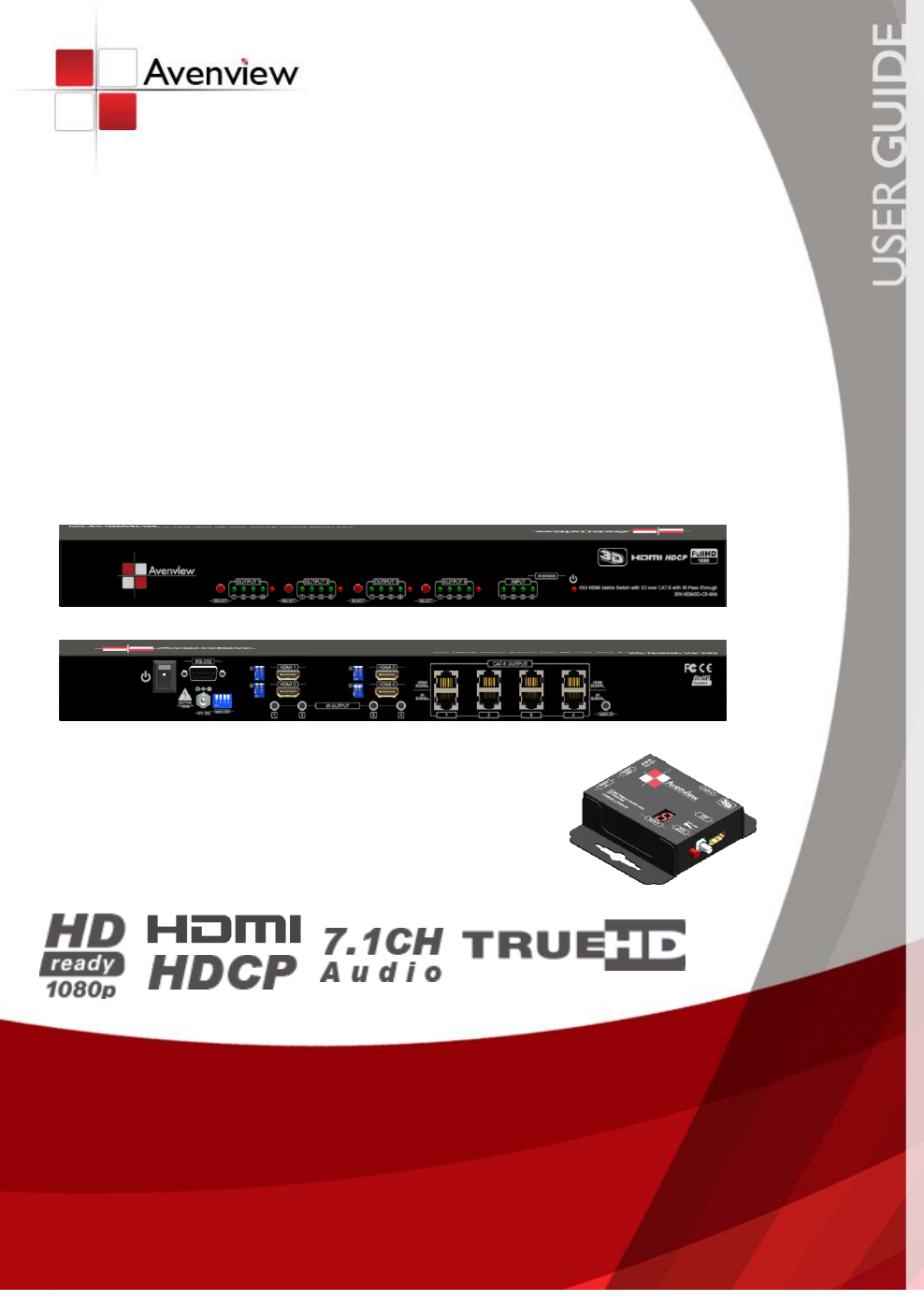
1.7 Panel Description 1.7.1 SW-HDM3D-C5-4X4 Front Panel 1. Port 1-4 SELECT: Push-in button for selecting input channel 2. Port 1-4: Input source channels mapping LED for each output channel 3. HP 1-4: Connection status indicator LED for each output channel 4. INPUT: Input source indicator LED 5. IR SENSOR: IR receiver 6. Power: Power indicator LED 1.7.2 SW-HDM3D-C5-4X4 Rear Panel 1. ON-OFF: Power ON/OFF 2. RS-232: RS-232 control port 3. +5V DC: 5V DC power jack 4.
1.7.3 HDM3D-C5SW-R 1. IR INPUT: Plug in IR receiver. 2. +5V DC: Spare power jack for over 60m transmission when the RX may need external power to work. 3. HDMI SIGNAL: Plug in the CAT5 connected to the respective A/V SIGNAL port on the SW-HDM3D-C5-4X4 4. IR SIGNAL: Plug in the CAT5 connected to the respective CHANNEL CONTROL port on the SW-HDM3D-C5-4X4 5. INPUT : Display the current showing HDMI source channel 6.
1.7.4 Dip Switch for EDID & Audio Settings (SW1 – SW4) DIP Switch Position PIN # 1 PIN # 2 OFF Video Audio Description Up to 1080p Surround Default Mode 1 1 – EDID up to 1080p video & surround sound audio output up to 7.
1.7.5 SW Main Dip Switch for Firmware Update DIP Switch Position PIN # 1 PIN # 2 PIN # 3 PIN # 4 Normal Operation Mode6 OFF OFF ON OFF Firmware Update Mode7 ON ON OFF OFF 6 Factory default for SW Main is pin#1-OFF[], pin#2-OFF[], pin#3-ON[], & pin#4-OFF[]. PLEASE MAINTAIN THIS SETTING AT ANYTIME FOR REGULAR USE! 7 Sequence for firmware update [1]. Power off the SW-HDM3D-C5-4X4. [2]. Set the DIP switch position to Firmware Update Mode. [3]. Power on the SW-HDM3D-C5-4X4.
1.8 IR Control Patch IR Transmitter Cable IR Receiver Cable IR Main The default location for IR emitter extension cable to transmit all IR command signals received from any of the four remote receivers to all of the HDMI sources. IR1 IR emitter extension cable connected here can only transmit IR command signals from the remote receivers that are setting at the input channel 1.
1.9 Installation (SW-HDM3D-C5-4X4) To setup Avenview SW-HDM3D-C5-4X4 follow these steps for connecting to a device: 1. 2. 3. 4. 5. 6. 7.
1.10 Operation and IR Control 1.10.1 Source Side 1.10.1.1Method A: Push-in Button Push the red switch button on output port to select which port to be changed. 1.10.1.2Method B: IR Remote Control Choose the output port you want to make channel switch from OUT1 to OUT4 then press 1-4 channel button to choose the HDMI input source shown on the chosen output display. www.avenview.
1.11 RS232 Serial Port Control Scan: Press Scan button, the machine will scan the all com port and show them. Select the RS232 serial port connected to the machine. And set device ID 255 is for all device. Only the same device id or 255 can get the command you sent. Press OK. Get the new status from the machine you select. Setting: Press Get button to read back device ID. Press Set button to write device ID. www.avenview.
Linkage: Press Linkage button to read back all status Open / Close : Press this button to Close or Open COM Port. Mapping Button: Select All Output: Select “set all output”, then select the source on main menu. You can quickly set all output to the same source. Unselect All Output: Release output selection. Select Input1~4-Output: Select Input Source. Then select the output port icon. For example: Select input source 1. Then select output port one and two.
Group setting First select output ports one by one. Then select the input source. The selected output ports change the setting at the same time. By using Terminal: Baud rate: Data length: Parity check: Stop bit: 9600 8bit No 1 1.11.
Section 2: Specifications Item Units Unit Description Description SW-HDM3D-C5-4X4 HDM3D-C5SW-R 4X4 HDMI Matrix Switch with 3D over CAT-5 with IR Pass-Through HDMI Matrix Switch with 3D Receiver HDMI Compliance Support HDMI Deep Color & full 3D HDCP Compliance Yes Video Bandwidth Single Link 225 MHz (6.
Notice 1. If the DVI or HDMI device requires the EDID information, please use EDID Reader/Writer to retrieve and provide DVI/HDMI EDID information. 2. All HDMI over CAT5 transmission distances are measured using Belden 1583A CAT5e 125MHz LAN cable and ASTRODESIGN Video Signal Generator VG-859C.3 3. The transmission length is largely affected by the type of LAN cables, the type of HDMI sources, and the type of HDMI display.
www.avenview.
Disclaimer While every precaution has been taken in the preparation of this document, Avenview Inc.