
User manual


Installation and User Manual ADPRO FastTrace-R by Xtralis
28 Doc 13972_03
3.1 Power Connection
The FastTrace-R is designed for 100-240 VAC 50-60Hz operation. Ensure mains supplies are
stable and are not subject to frequency changes, voltage spikes etc. The use of mains
suppression units or even UPS (Uninterrupted Power Supply) systems is recommended to
ensure stable voltages.
Maximum input current is 5 amps during power up and 1 amp during normal operation. Typical
unit power consumption when fully optioned is 100 W.
3.2 Connecting Communication Devices
FastTrace-R provides a number of interfaces for connecting communications devices to allow
remote access to the system for setup and review of stored information. These interfaces are
available via the COMMS 1, COMMS 2 and NETWORK connectors on the rear panel.
In general, there are three primary types of communication links available; dial-up, dedicated or
network. Both dial-up and dedicated links can be either analogue (PSTN) or digital (ISDN),
depending of the type of connections available at the site.
There are a variety of different networks that are available, and with the appropriate interface the
FastTrace-R can work over the majority of them.
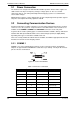
3.2.1 COMMS 1
COMMS 1 is a serial communication port and is used to connect to modems and terminal
adaptors to support PSTN and ISDN links at data rates up to 230 kps. The 25-pin D connector
pins are wired as shown below.
Figure 32: Comm1 Pin Numbers
Table 2: Comm Port 1 Connection
V.24 Nam e Pin Direction V.24 Description
SGND 1 - Shield
TXD 2 O Transmit data
RXD 3 I Receive data
RTS 4 O Request to send
CTS 5 I Clear to send
DSR 6 I Data Set Ready
GND 7 - Signal ground
DCD 8 I Carrier detect
9I