
User manual


ADPRO FastTrace-R by Xtralis Installation and User Manual
Doc 13972_03 19
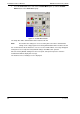
3. To check the defaults, select the FT-R default site entry and click Edit. The Site
Configuration details are shown with the default values, as follows:
Figure 23: Default Ethernet Site Configuration
Figure 24: Default Serial Site Configuration
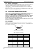
2.8 FastTrace-R Configuration
1. Before powering the FastTrace-R unit on, check that the factory DIP-Switch settings are
correct refer to Section 3 for more details.
The location of the DIP-Switch is on the rear of the FastTrace-R unit at the bottom,
underneath the camera connections and next to the monitor connector.
2. Set the DIP-Switch 10 to the appropriate video standard for the region:
- (ON - NTSC, OFF - PAL).
3. Ensure the airflow vents into the side of the FastTrace-R unit are not blocked.
4. Connect the crossover Ethernet cable between the FastTrace-R Ethernet port and the PC’s
Ethernet port or the null modem cable between the Comm2 port and the PC’s serial comms
port.
5. Once DIP-Switch settings are verified and all cables are connected, plug in the mains
power cable.