VSSI-PRO Version 13 VIDEO SERIAL SYNCHRONOUS ATM INTERFACE Operation Manual APRIL 2006 1
VSSI-PRO WARNING! RISK OF ELECTRICAL SHOCK! DO NOT OPEN! TO PREVENT FIRE OR ELECTRIC SHOCK, DO NOT REMOVE COVER. NO USER SERVICEABLE PARTS INSIDE. REFER SERVICING TO QUALIFIED PERSONNEL. WARNING! THIS EQUIPMENT GENERATES, USES, AND CAN RADIATE RADIO FREQUENCY AND IF NOT INSTALLED AND USED IN ACCORDANCE WITH THE INSTRUCTION MANUAL MAY CAUSE INTERFERENCE TO RADIO COMMUNICATIONS.
CONTENTS Features...................................................................................................................................................................6 Specifications..........................................................................................................................................................7 Connecting the VSSI-Pro.........................................................................................................................................
CONTENTS Alarm Outputs (Continued) Flag Type......................................................................................................................................38 Flag Duration................................................................................................................................38 Triggered Text...............................................................................................................................39 Test/Demo Mode.............................
CONTENTS FIGURES (Continued) Figure 17 : The VSSI-Pro Connections to TCPIP 232 Adapter...............................................................................17 Figure 18 : TCPIP Interface Sub-Menu................................................................................................................18 Figure 19 : TCPIP Format I Sub-Menu..................................................................................................................18 Figure 20 : TCPIP Interface Sub-Menu.....
FEATURES FEATURES The VSSI-Pro ATM Interface allows one unit to connect to all ATMs and Networks by all possible methods to support any banking requirement. ............Easy Menu-driven Setup and Programming ............Number of Display Lines Programmable ............Supports DVR Command Set for Auto Search Capability ............Supports the AVE Networker & Hydra for connection to many 3rd party DVR manufacturers ............Programmable on-screen time/date display.
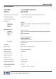
SPECIFICATIONS SPECIFICATIONS Video In (BNC) Video Out (BNC) Video S / N Video B / W 1V P-P Terminated 75 ohms +/- 20% 1V P-P Terminated or Unterminated better than 50dB better than 7MHz Power (DC Coax 2.1mmx5.5mm) 9-12VDC 130mA nominal, 150mA maximum with Alarms Battery Backup NiMH 1 year with 24 hour charge Serial Ports (DB-9) Female Serial Port 1 Baud Rate Word Length Parity Stop Bits RS-232C Auto, 135, 150, 300, 600, 1200, 2400, 4800, 9600, 19.2K, 28.8K, 38.
SPECIFICATIONS Watchdog Timer Hardware and Software Temperature Rating Humidity 0 – 50 degrees Celsius 32 – 122 degrees Fahrenheit Non-Condensing 85% RH VSSI-Pro 0.70 Kg or 1.55 lbs Beige Metal Enclosure 130L x 127W x 38H (mm) 5.12L x 5W x 1.5H (in) Maximum Size with Connectors 145L x 127W x 43H (mm) 5.7L x 5W x 1.7H (in) Packed in White Box with Manual 1.20 kg or 2.65 lbs 340L x 190W x 85H (mm) 13.4L x 86.2W x 3.
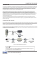
CONNECTING THE VSSI-PRO INTRODUCTION The VSSI-Pro is designed for controlling loss and fraud at the ATM terminal. When connected between an ATM and a recording device such as a VCR or DVR it monitors the data stream, overlaying the ATM’s transaction data onto the video picture to get a complete picture of every transaction. The data can also be discretely sent to a remotely located serial printer. The video input can be virtually any baseband or composite video source.
CONNECTING THE VSSI-PRO ATM TO VSSI-PRO INSTALLATION Locate the connector on the ATM’s modem and loosen the 2 retaining screws, then quickly plug in the appropriate DB25 connector of the triport into the modem. Next plug the modem cable into the other DB-25 connector of the triport, and plug the DB-9 connector into the VSSI-Pro. NOTE " Make sure no one is operating the ATM when you disconnect the DB-25 connector. IMPORTANT ✓ The input video level must be 1V P-P.
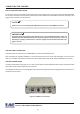
CONNECTING THE VSSI-PRO Cable and Connection: Pin-out of the DB-9 connector on the VSSI-Pro.
CONNECTING THE VSSI-PRO To interface with a camera port, the following cable should be used. Cable between ATM camera interface and VSSI-Pro: CAMERA INTERFACE DB-25 (MALE) DB-9 (MALE) 2 3 7 WITH DATA-OUT OPTION 3 6 5 DB-9 (MALE OR FEMALE) 8 5 2 5 DB-25 (MALE OR FEMALE) 3 7 Table 3: Pin-Out of the ATM Camera Interface DB-9 Male Connector DB-25 Male EXTERNAL ALARM OUTPUT You will be able to tie your exceptions to one open collector hard alarm output.
PROGRAMMING THE VSSI-PRO A FEW WORDS ABOUT PROGRAMMING The VSSI-Pro is programmed by pressing and releasing specific combinations of the four front panel push-buttons. Via these four simple buttons, all of the powerful programming features of the VSSI-Pro are available to you. A video source and a monitor must be connected in order for you to see the programming menus. The following sections provide detailed programming instructions.
PROGRAMMING THE VSSI-PRO Changing the Horizontal Position Down Up Set Reset Figure 5: Four Front Pannel Push-Buttons of VSSI-Pro (Up) 1. Press and hold the “Up” button. 2. Press and release the “Reset” button. 3. Release the “Up” button. 4. Press “Down” or “Up” to move the text block. 5. When the choice is made, press and release the “Set” button. Changing the Vertical Position Down Up Set Reset Figure 6: Four Front Pannel Push-Buttons of VSSI-Pro (Set) 1. Press and hold the “Set” button. 2.
PROGRAMMING THE VSSI-PRO PROGRAMMING MENUS To access the main-menu of the VSSI-Pro, simultaneously hold down the “Down” and “Up” buttons, press and release the “Reset” button, and then release the “Down” and “Up” buttons. This will take you to the main programming menu. To navigate through this menu, press the “Down” or “Up” button to position the cursor in front of the desired item and then press “Set” to select the item and access any sub-menus for that item.
PROGRAMMING THE VSSI-PRO This sub-menu is selected when connecting to SNA or X.25 modem taps. The most common is FORMAT I but if the data does not display in a pleasing format try FORMAT II-IV. The CAT ELF is for the Citibank ATM network only. SDLC FORMAT I SDLC FORMAT II SDLC FORMAT III SDLC FORMAT IV CAT ELF EXIT Journal printer taps take the data from the journal or reciept printer and displays that data. This data is either RS-232C or a propietary variation thereof.
PROGRAMMING THE VSSI-PRO TCPIP 232 Adapter Connections 1. Remove the ATM LAN Cable which is connected direct to the ATM and then immediately plug it in to the TCPIP 232 Adapter. Loop the LAN cable which came with TCPIP 232 Adapter via the RJ-45 Port on the TCPIP 232 Adapter rear panel to the ATM. Delay in doing this might cause the ATM to go off-line. If this happens then wait for the ATM to automatically come back on-line. 2.
PROGRAMMING THE VSSI-PRO The TCPIP INTERFACE sub-menu: TCPIP FORMAT I TCPIP DEBUGGING EXIT Figure 18: TCPIP INTERFACE Sub-Menu 1. Press the “Up” or “Down” button to move the cursor to “TCPIP FORMAT I” and press “Set” to enter and change the IP address to the same as ATM’s IP address. EXAMPLE: If the ATM’s IP address is 192.168.0.141, set the address on the TCPIP 232 Adapter using this menu. IP ADDRESS 1 192 IP ADDRESS 2 168 IP ADDRESS 3 0 IP ADDRESS 4 141 EXIT Figure 19: TCPIP FORMAT I Sub-Menu 2.
PROGRAMMING THE VSSI-PRO CUSTOM The custom settings are for special programming done for various customers to format the display or to interface to a proprietary network exclusive to that customer. The following sub-menu will appear: CUSTOM 1 CUSTOM 2 CUSTOM 3 CUSTOM 4 CUSTOM 5 CUSTOM 6 CUSTOM 7 EXIT Figure 22: CUSTOM Sub-Menu SCREEN SETUP On the main-menu, press the “Up” or “Down” button to move the cursor to “SCREEN SETUP” and press “Set”.
PROGRAMMING THE VSSI-PRO CLOCK To program the clock's functions, use the “Up” and “Down” buttons to move the cursor to “CLOCK” and press “Set”. The following sub-menu will appear: T/D DISPLAY TIME DISPLAY DATE FORMAT DAYLIGHT SAVING SET TIME/DATE RESET TIME/DATE T/D LOCKING EXIT ON 12 HOUR DD/MM/YY DISABLE ON Figure 24: CLOCK Sub-Menu NOTE " Enabling the clock limits the number of display lines to 10 maximum. T/D DISPLAY turns the time/date display on or off.
PROGRAMMING THE VSSI-PRO MORE ON TIME/DATE LOCKING If the time/date locking is turned on, the VSSI-Pro will monitor the incoming data string. If it finds a valid time and date in one or two consecutive lines, it will set the clock to whatever time/date it finds. A valid time has the following formats: hh:mm, hh:mm:ss hh:mmAM, hh:mm:ssAM hh:mmPM, hh:mm:ssPM where hh is a number between 0 and 24 or 0 and 12 if either AM of PM is present.
PROGRAMMING THE VSSI-PRO When the desired time/date is displayed, press the “Up” and “Down” buttons simultaneously to enter the title into memory and return to the menu. The white boxes will disappear and your title will be displayed as it will appear on-screen. NOTE " Remember, enabling the titler will limit text insertions to 10 lines maximum, and with the clock on then 9 maximum. EXIT Press the “Up” or “Down” button to move the cursor to “EXIT” and press “Set” to return to the previous menu.
PROGRAMMING THE VSSI-PRO DISPLAY LINES Choices: 1 through 11 You have the choice of how many lines of text to display on-screen for register transactions. The choices are 1 through 11. Press the “Up” or “Down” button to move the cursor to “DISPLAY LINES” and press “Set”. The cursor will begin flashing. Press the “Up” or “Down” button to cycle through the values and press “Set” when the desired value is displayed.
PROGRAMMING THE VSSI-PRO DISPLAY Choices: ON, OFF You have the choice to globally turn on or off the complete VSSI-Pro text insertion function. This means no data will be visible on the monitor if you select DISPLAY “OFF”. However, if you select the DISPLAY “OFF”, you can still command each exception independently to either display on-screen or not through its program setup sub-menu under EXCEPTION REPORTS.
PROGRAMMING THE VSSI-PRO RX BAUDRATE Choices: AUTO, 150, 300, 600, 1200, 2400, 4800, 9600, 14.4K, 19.2K, 28.8K, 38.4K. The default is 2400. Press the “Up” or “Down” button to move the cursor to “RX BAUDRATE” and press “Set”. The cursor will start flashing. Press the “Up” or “Down” button to cycle through the values and press “Set” when the desired value is displayed. Note that changing the RX BAUDRATE value simultaneously changes the TX BAUDRATE value.
PROGRAMMING THE VSSI-PRO PORT A : B Again, there is probably no need for you to access this menu as it should be used for testing purposes only. You should rely on the setting chosen in ATM SELECT, but we will provide a brief overview of this menu. Press the “Up” or “Down” button to move the cursor to “PORT A : B” and press “Set”. The following sub-menu will appear: ASYNC BISYNC SDLC EXIT Figure 29: Port A : B Sub-Menu ASYNC Press the “Up” or “Down” button to move the cursor to “ASYNC” and press “Set”.
PROGRAMMING THE VSSI-PRO DATA BITS Choices : 7 or 8 Press the “Up” or “Down” button to move the cursor to “DATA BITS” and press “Set”. The cursor will start flashing. Press the “Up” or “Down” button to toggle between values and press “Set” when the desired value is displayed. In addition to each item in this sub-menu and in the sub-menus for BISYNC and SDLC will be the settings for these formats, one of which you chose in the ATM SELECT sub-menu. The address settings are ASYNC or 0 through 254.
PROGRAMMING THE VSSI-PRO NOTE " Added to DATA ENCODE in this sub-menu is the choice of AUTO along with NRZ, NRZI, NRZID. Otherwise the settings available are the same as in the BISYNC or ASYNC menus. EXIT Press the “Up” or “Down” button to move the cursor to “EXIT” and press “Set” to return to the previous menu.
PROGRAMMING THE VSSI-PRO PRINTER or DVR OUTPUT There may be situations where you do not want tellers or other employees to know what triggers an exception. In this case, the VSSI-Pro provides a seperate output that will send data to a remotely located serial printer. If you turn the onscreen display off and the output on and you have a remote serial printer hooked up to the VSSI-Pro, then whenever an exception is reported it is sent out to the serial printer only.
PROGRAMMING THE VSSI-PRO Example: Define “WITHDRAWAL” as an exception string in Exception No. 2 with the DISPLAY “ON” and define RANGE “100.001000.00” and define OPERATOR ”IN”. 11:09:45A 11:09:45 A 11:13:12 A 11:20:23 A 9/12/05 9/12/05 9/12/05 9/12/05 MON REC WITHDRAWAL150.00 GDSFDFDFL000 WITHDRAWAL250.
PROGRAMMING THE VSSI-PRO DEST ID and SRC ID Choices: 1 through 32 Press the “Up” or “Down” button to move the cursor to “DEST ID” or “SCR ID” and press “Set”. The cursor will start flashing. Press the “Up” or “Down” button to toggle between values and press “Set” when the desired value is displayed. EXIT Press the “Up” or “Down” button to move the cursor to “EXIT” and press “Set” to return to the previous menu.
PROGRAMMING THE VSSI-PRO TIME SEARCH TIME SEARCH SETTING NOTE " For any exception you must program Display “ON” for any exception data to be saved in the Exception History. USING TIME SEARCH FUNCTION 1. Press the “Up” or “Down” button to move the cursor to “TIME SEARCH” and press “Set”. The following sub-menu will appear: WITH DRAWAL 11:09:45 A 9/12/05 WITHDRAWAL150.00 11:20:23 A 9/12/05 WITHDRAWAL250.00 EXIT 12-09-2005 11:30:05 Figure 39: TIME SEARCH Sub-Menu 2.
PROGRAMMING THE VSSI-PRO OUTPUT EXCEPTIONS This selection allows you to have the buffered exceptions sent out for printing. This is a global setting for all exceptions, but you also need to turn on the output for each independent exception. CLEAR HISTORY This selection clears all the buffered exceptions and resets the TOTAL EXCEPTIONS counter. EXIT Returns you back to the EXCEPTION REPORT menu. SET EXCEPTION Press the “Up” or “Down” button to move the cursor to “SET EXCEPTION” and press “Set”.
PROGRAMMING THE VSSI-PRO DISPLAY Choices: ON, OFF This display item lets you control whether or not a particular exception is displayed on the video monitor or not. If you do not turn on the exceptions display here, you will not have the on-screen flag and consequently no record of the exception when it occurs. To make your selection, press the “Up” or “Down” button to move the cursor to “DISPLAY” and press “Set”. The cursor will start flashing.
PROGRAMMING THE VSSI-PRO WILDCARD: The wildcard symbol “•”, a centered dot, excepts on any data in that position. Press the “Up” or “Down” button to move the cursor to “EXCEPTION STRING” and press “Set”. The first position of the 20 character exception will become active by flashing. Program in your exception string. NOTE " Remember to enter your exception string based on the way the data prints to video, including spaces, and remember pressing “Set” advances to the next position.
PROGRAMMING THE VSSI-PRO NAVIGATING THE RANGE AND THE EXCEPTION STRING Before you define your range, we need to explain how to navigate through the range and exception string using the front panel switches. To program the range, press the “Up” or “Down” button to move the cursor to “RANGE” and press “Set”. The first “0” in the range starts to flash. This means it is active and ready for programming.
PROGRAMMING THE VSSI-PRO NOTE " The VSSI-Pro provides one hard alarm output to trigger other devices such as VCR’s, DVR’s, QUADS, Enunciators, LED’s, or other alarming devices. The ALARM OUTPUTS menu controls not only the formatting of the external alarms, but also the formatting of the onscreen flags assigned to individual exceptions. ALARM NO. Choices: 1 through 16 You have the ability to tie Alarm 1 to any of the programmed exceptions to trigger an external device.
PROGRAMMING THE VSSI-PRO Pin 1 on the DB-9 is Alarm 1 and Pin 5 is ground. To select the alarm trigger that you want to program, press the “Up” or “Down” button to move the cursor to “ALM TRG” and press “Set”. The cursor will start flashing. Press the “Up” or “Down” button to cycle through the values and press “Set” when the desired value is displayed. NORMAL STATE Choices: NO, NC There are two choices: NO (Normally Open) or NC (Normal Closed).
PROGRAMMING THE VSSI-PRO TRIGGERED TEXT Triggered Text is a data string that associates with one of the 16 alarms. When the alarm is triggered by a source, the associated string is sent out and/or displayed if enabled respectively. Each Triggered Text can contain up to 40 printable ASCII data. If non-printable data (control code) is included, each control code occupies 3 printable spaces. Therefore only 13 control codes maximum can be programmed in one Triggered Text program control escape etc.
PROGRAMMING THE VSSI-PRO TEST/DEMO MODE The Test/Demo Mode provides you with several ways to test the VSSI-Pro and show its capabilities as an ATM interface. There is no actual programming in this menu that you need to do now or settings that you would change. You will probably only run the tests for troubleshooting purposes, and the demos would be helpful for demonstrating the VSSI-Pro to a customer without actually having to access an ATM.
PROGRAMMING THE VSSI-PRO NOTE " In any of these tests, you can pause the data scrolling by holding down either the “Up”or “Down” button. The VSSI-Pro is now waiting for data from the ATM. Enter a transaction. If the VSSI-Pro is receiving data, it will appear in three separate lines, scrolling from right to left across the bottom of the on-screen display. The first line is the transaction information. The second and third lines represent the HEX equivalent of the data in the first line.
PROGRAMMING THE VSSI-PRO BAUD RATE SCAN There may be times when the baud rate cannot be detected on start-up. In the Baud Rate Scan test, you can scan for the baud rate of your interface. Press the “Up” or “Down” button to move the cursor to “BAUD RATE SCAN” and press “Set”.
PROGRAMMING THE VSSI-PRO TRANSMIT [ TX ] TEST Press the “Up” or “Down” button to move the cursor to “TRANSMIT [ TX ] TEST” and press “Set”. The following display will appear (example only): PROTOCOL : RX BAUDRATE : TX BAUDRATE : DATA ENCODE : ASYNC 19200 19200 NRZ ASCII Figure 52: TRANSMIT [ TX ] TEST Display Press “Set” to return to the previous menu. EXIT Press the “Up” or “Down” button to move the cursor to “EXIT” and press “Set” to return to the previous menu.
PROGRAMMING THE VSSI-PRO CAPTURE TO MEMORY Press the “Up” or “Down” button to move the cursor to “CAPTURE TO MEMORY” and press “Set”. The following display will appear (example only): PROTOCOL : ASYNC RX BAUDRATE : 19200 TX BAUDRATE : 19200 DATA ENCODE : NRZ ASCII CAPTURE DATA TO MEMORY CHA RX BYTE : 00000 CHB RX BYTE : 00000 Figure 55: CAPTURE TO MEMORY Display Press “Set” to return to the previous menu. DUMP TCP/IP Press the “Up” or “Down” button to move the cursor to “DUMP TCP/IP” and press “Set”.
PROGRAMMING THE VSSI-PRO TRANSACTION BEGIN TRANS 5697 05 / 26 / 05 12:32 059 0026 TST ATM RALEIGH 3100 HIGHWOODS BLVD RALEIGH # 2 NC 05 / 19 / 05 BUSINESS DATE CODE*SERIAL AMOUNT 5697 10.00 WITHDRAWAL FROM CHECKING CHK BAL $21.601.42 TRANSACTION END Figure 58: ATM DEMO Display VERSION IDENTIFICATION When selected, this will display the current VSSI-Pro version and revision number. VSSI PRO 05 / 26 / 2005 V13.
PROGRAMMING THE VSSI-PRO DOWNLOAD/UPLOAD SETUP USING VSSI-PRO TO VSSI-PRO To insure that the DOWNLOAD/UPLOAD process is accomplished, you need to access the programming menus for both VSSI-Pros, so each VSSI-Pro needs a video input and a monitor. The optimum way to perform the DOWNLOAD/ UPLOAD process would be to have a system set up with two separate cameras and monitors and the programmed VSSI-Pro with the download data cable attached.
PROGRAMMING THE VSSI-PRO NOTE " The Download/Upload feature can only be used on VSSI-Pro's with the same software revision level. To proceed with the DOWNLOAD/UPLOAD SETUP, we will configure the UNPROGRAMMED VSSI-Pro first. From the main-menu, press “Up” or “Down” to move the cursor to “DOWNLOAD/UPLOAD SETUP” on the menu on the right side of the screen. Press “Set”.
PROGRAMMING THE VSSI-PRO The count will end at 100. When this prompt clears the screen, the data transfer is complete. Press “Reset” to exit this menu on both VSSI-Pro’s. Now go to the main-menu of the previously UNPROGRAMMED VSSI-Pro on the right side of the screen. Enter the EXCEPTIONS menu. You should see your exceptions and other programmed data just as they were on the original PROGRAMMED VSSI-Pro.
DATA DUMP CONNECTIONS APPENDIX A DATA DUMP CONNECTIONS To execute a data dump you will have to connect wires from the DB-9 connector of the VSSI-Pro to either Com 1 or Com 2 of a computer, using the following pin-out diagram: SDLC / BISYNC CAMERA PORT / JOURNAL / TCPIP Com 1 (DB-9) Com 2 (DB-25) 3 8 2 3 5 5 5 7 Table 1A: Data Dump Connections Triport DB-9 Connector ATM RG-59U CAMERA MODEM VSSI-PRO DB-9 Connector COM 1 (DB-9) COM 2 (DB-25) RG-59U MONITOR Figure 1A: Data Dump Connect
APPENDIX B PROBLEM SOLVING GUIDE PROBLEM SOLVING GUIDE This section contains a Problem Solving Guide and additional information regarding AVE's interfaces, cables, tips, and special applications. NOTE " Before attempting to install your system, we highly encourage you to get your customer to demonstrate to you that their ATM is operating properly. No data on screen: 1. Press the reset button on the front panel. 2. Incorrect protocol selected in the ATM SELECT Menu. 3. Data cable is miswired.
MASTER RESET THE VSSI-Pro APPENDIX C MASTER RESET THE VSSI-PRO Simultaneously press and hold down the “Down”, “Up” and “Set” buttons. While holding these three buttons down, press and release the “Reset” button and then release the other three. Our copyright notice will appear and then disappear and the message “SET UP” will appear. Go into the ATM SELECT menu and chose your format. Then have someone perform a transaction on the ATM.
APPENDIX D FREQUENTLY ASKED QUESTIONS FREQUENTLY ASKED QUESTIONS REGARDING ATM INTERFACING My customer is changing ATMs; will the VSSI-Pro they have work on the new ATM? This is a tricky one. There may be other versions of software needed to work with different ATM formats. The probability the VSSI-Pro will work with a new system is relatively high, especially if it’s Version 11 based. Call AVE’s Product Support Specialists for additional help along these lines.
RS-485 NETWORKER APPENDIX E RS-485 NETWORKER The RS-485 Networker is designed to convert the RS-232 serial port output of the VSSI-Pro to be a poll/select network. This allows all the transaction data to be collected by one computer for up to 64 VSSI-Pros. APPLICATION Many users of the VSSI-Pro want to capture all the transaction data from several units to one device. The RS-485 Networker allows all data from up to 64 VSSI-Pros to be recorded on one PC or sent to one DVR.
APPENDIX F PC SOFTWARE WITH ATM DATA The simple to install and use PC Software allows up to 64 VSSI-Pro ATM Interfaces to be configured on an RS-485 network and report all the transaction data back to a single monitoring computer. This Windows based software can be configured to display in a windowing horizontal format below or tiling in a vertical format.
HARD ALARM OUTPUT APPENDIX G HARD ALARM OUTPUT The Alarm Output provides one open collector transistor alarm output to trigger alarming devices. Upon an Exception, a VSSI-Pro can be programmed to trigger a VCR to go to its fastest record time, have a Quad go full screen, home a switcher, trigger a preprogrammed PTZ, or provide visual or audible alarms. Following are some basic circuit designs to take advantage of the Alarm Output.
APPENDIX H TRIPORT AND ADAPTER CABLE Triport and Adapter Cable Triports are typically used to passively tap data from a serial device. A Triport has three connectors, either 2DB-25's back to back or 2DB-9's and an additional DB-9 male which connects to the VSSI-Pro. The Triport ( and cable ) supplied with the VSSI-Pro is the ATM 2 Channel Triport. The following pin-out diagram for the cable is available for troubleshooting purposes.
PIN ASSIGNMENT FOR TIME SEARCH FUNCTION APPENDIX I PIN ASSIGNMENT FOR TIME SEARCH FUNCTION VSSI-PRO DMS 3001 and DVR TXDA 8 GND 5 RXD 2 GND 5 Figure 1I: Pin Assignment for Time Search Function TCPIP 232 ADAPTER CONNECTION PIN-OUT ROUTER TCPIP 232 TXD3 RXD2 GND5 RXD2 TXD3 GND5 GND5 GND5 VSSI-PRO RTS9 TXDA8 RTS7 RXD3 ATM NETWORKER Figure 2I: TCPIP 232 Adapter Connection Pin-Out SDLC / BISYNC / ASYNC ATM CONNECTION PIN-OUT RXDB2 RXCB15 RXDA3 RXCA17 GND7 ATM RXDB2 RXCB7 RXDA6 RXCA4 GND5 2 7
APPENDIX J LIMITED WARRANTY LIMITED WARRANTY (Terms and Conditions) For 2 Years from the date of shipment, Seller warrants to Buyer that the Product is free from defects in material or workmanship under normal use and service. Equipment manufactured by other than Seller but furnished by Seller carries the same warranty to Buyer as Seller receives from the other manufacturer, notwithstanding any provision to the contrary.
LIMITED WARRANTY APPENDIX J SELLER SHALL NOT BE LIABLE FOR ANY SPECIAL, DIRECT INCIDENTAL OR CONSEQUENTIAL DAMAGES OF A COMMERCIAL NATURE ARISING OUT THE USE OF OR INABILITY TO USE SELLER’S PRODUCT BY REASON OF THE FACT THAT SUCH PRODUCT DOES NOT CONFORM TO THE CONTRACT OR TO ANY EXPRESS OR IMPLIED WARRANTY.
APPENDIX K NOTES VSSI-Pro VIDEO SERIAL ATM INTERFACE 60
NOTES APPENDIX K VSSI-Pro VIDEO SERIAL ATM INTERFACE 61
APPENDIX K NOTES VSSI-Pro VIDEO SERIAL ATM INTERFACE 62
NOTES APPENDIX K VSSI-Pro VIDEO SERIAL ATM INTERFACE 63
AVE Multiview USA 2000 West Governors Circle Suite E, Houston, Texas 77092 Tel: 1-281-443-2300 Fax: 1-281-443-8915 Email: sales@aveusa.com http://www.americanvideoequipment.com AVE Multiview UK Granyte House, Delamare Road Cheshunt, Hertfordshire EN8 9SP Tel: 440-870-770-9323 Fax: 440-870-770-9363 Email: enquiries@ave-uk.com http://www.multiview.net AVE (Thailand) Co., Ltd.