
User manual

ADPRO FastTx by Xtralis Installation and User Manual
Doc 11949_06 41
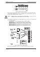
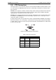
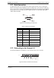
Figure 43: Alarm Connector Pinouts
Wire connections from the alarm switches are made by using the screw terminal contact strips
supplied with the ADPRO FastTx. For ease of installation, the screw terminal blocks slide over
the connector pins when the wiring is complete.
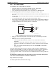
Caution: DO NOT attempt to solder directly onto the connector pins, as this may cause heat
damage to the connector housing or to the interface PCB.
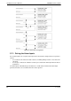
The setup options for alarm inputs are described with reference to the ‘rest’ or non-alarm position
of a set of switch contacts:
• Normally Open - needs a closing alarm contact to activate an alarm
• Normally Closed - needs an opening alarm contact to activate an alarm
• SEOL Normally Open - Single End of Line termination with N/O contacts
• SEOL Normally Closed - Single End of Line termination with N/C contacts
• DEOL Normally Open - Dual End of Line termination with N/O contacts
• DEOL Normally Closed - Dual End of Line termination with N/C contacts
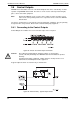
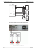
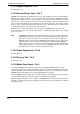
Figure 44: External Sensor Wiring Circuits
Please refer to Specifications on page 121 for voltage requirements and considerations.