
User manual

Installation and User Manual ADPRO FastTx by Xtralis
94 Doc 11949_06
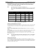
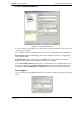
Alarm Logic
The Alarm Logic option is used to set up the logical order in which Alarm Inputs are treated
before an alarm event is declared to be ‘valid’.
Up to ten detectors can be associated with any one camera.
Options: When ANY input occurs, Only when ALL inputs occur
Default: When ANY input occurs
From the drop-down list, select whether this camera will be triggered when ANY of the inputs are
triggered (i.e. any one of the events defined in the list below will cause an Event reaction within
ADPRO FastTx) or when ALL inputs are triggered (i.e. when all inputs are triggered
simultaneously). When the ALL option is selected, the Hold Time for the various inputs as
previously defined (in Connected Equipment / Alarm Inputs) will also be used.
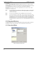
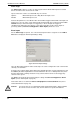
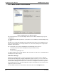
Event Inputs
For the Alarm Logic to operate, one or more Event Inputs must be assigned. Use the Add to
list button to display the Event Input Settings dialog.
Figure 93: Event Input Settings
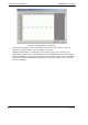
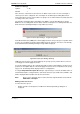
Up to 10 different Event Inputs and associated presets can be configured for each camera in the
currently selected Mode.
Select the type of Event Input (either Alarm Input, Activity Detection or Transaction Device) and
the Source (the Alarm Input Channel or Video Channel in the case of Activity Detection). Note
that any alarm input or activity detection on any camera channel can be used to trigger any
camera on the system.
The Source for an Event Input is defined by the settings in Connected Equipment / Alarm
Inputs (refer to Alarm Inputs on page 81).
Transaction devices are defined in Connected Equipment / Transaction Devices (refer to
Transaction Devices on page 78).
Caution: If a camera has an associated Alarm Input and the Alarm Input is triggered whilst
the camera is in the no video state, then no alarms are reported via dial out.