ADPRO FastTx by Xtralis Installation and User Manual March 18, 2010 Part 201820.
ADPRO FastTx by Xtralis Installation and User Manual Disclaimer The contents of this document are provided on an "as is" basis. No representation or warranty (either express or implied) is made as to the completeness, accuracy or reliability of the contents of this document. The manufacturer reserves the right to change designs or specifications without obligation and without further notice.
Installation and User Manual ADPRO FastTx by Xtralis Document Conventions The following typographic conventions are used in this document. Convention Description Bold Used to denote: emphasis Used for names of menus, menu options, toolbar buttons Italics Used to denote: references to other parts of this document or other documents.
ADPRO FastTx by Xtralis Installation and User Manual Compliance of Power Cord Caution: If the power cord supplied with the ADPRO FastTx is not suitable for your local power connection, do not modify the cord. Please purchase a power cord that has the safety approvals appropriate for your country. Connection to Other Equipment Caution: All interface ports on the ADPRO FastTx must be only connected to other equipment or systems that are Safety Extra Low Voltage (SELV) rated.
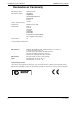
Installation and User Manual ADPRO FastTx by Xtralis Declaration of Conformity Manufacturer's Name: Manufacturer's Address: Xtralis AG Pty Ltd 4 North Drive Virginia Park, 236-262 East Boundary Road East Bentleigh VIC 3165 Australia. declares, that the product(s): Product Name: Model Number: ADPRO FastTx by Xtralis AFTX-10 AFTX-20 AFTX -10-D AFTX-20-D AFTX-10-DRU AFTX-20-DRU D = Down-the-Coax Telemetry Module DRU = Digital Recording Upgrade Product Options: All meet the Standards detailed below.
ADPRO FastTx by Xtralis Installation and User Manual Contents 1 Introduction ...................................................................................................................................... 1 2 ADPRO FastTx Setup Instructions ................................................................................................. 3 2.1 Physical Location ................................................................................................................ 3 2.
Installation and User Manual ADPRO FastTx by Xtralis 3.4 Video Input Connections .................................................................................................. 36 3.4.1 Video Input Requirements ..................................................................................... 37 Maximum Camera Input Cable Length .................................................................. 37 3.5 Video Output ......................................................................................
ADPRO FastTx by Xtralis Installation and User Manual Monitor Settings ..................................................................................................... 78 4.3.11 Transaction Devices ............................................................................................ 78 4.3.12 Transparent Data Port .........................................................................................79 4.3.13 Alarm Inputs .......................................................................
Installation and User Manual ADPRO FastTx by Xtralis Figure 11: Select Modem Driver from Disk .......................................................................................... 13 Figure 12: Install from Disk .................................................................................................................. 13 Figure 13: Select Modem COM Port .................................................................................................... 14 Figure 14: Installation Warning ......
ADPRO FastTx by Xtralis Installation and User Manual Figure 68: Call List Menu ..................................................................................................................... 68 Figure 69: Call List (Ethernet-left, Serial-right) Properties.................................................................... 68 Figure 70: Connected Equipment Menu............................................................................................... 70 Figure 71: Cameras Menu....................
Installation and User Manual ADPRO FastTx by Xtralis List of Tables Table 1: Firewall Ports ......................................................................................................................... 26 Table 2: Comm Port 1 Connection....................................................................................................... 29 Table 3: Comm Port 2 Connection.......................................................................................................
ADPRO FastTx by Xtralis 1 Installation and User Manual Introduction ADPRO FastTx by Xtralis is an advanced, high performance remote video audio transmission system. Available in models with 10 or 20 video inputs, ADPRO FastTx provides outstanding transmission speed and picture quality for remote security and surveillance applications where secure, event-driven transmission from multiple cameras is required.
Installation and User Manual ADPRO FastTx by Xtralis Optional second screen (depends on OS support) Modem or Terminal Adaptor 100/10baseT Dial-Up or Point-to-Point Communication Network TCP/IP LAN/WAN Modem or Terminal Adaptor ADPRO FastTx Remote Site(s) General Relay Output Video Inputs Mode Select Input GP Serial Ports STATUS Alarm Inputs Access/ Secure Input 100/10baseT Ethernet TM Control Outputs POWER Monitoring Site Video Video Colour or Monochrome Cameras, Video Video Doors
ADPRO FastTx by Xtralis 2 Installation and User Manual ADPRO FastTx Setup Instructions This chapter contains instructions to setup the ADPRO FastTx. 2.1 Physical Location The location within the protected premises of the ADPRO FastTx should be considered carefully and the following notes are provided for guidance. • Physical Security - The ADPRO FastTx should be located where it will remain secure under all conditions, even when the premises are open or occupied.
Installation and User Manual ADPRO FastTx by Xtralis 2.2.1 Power Conditioners and Surge Arresters The use of an Uninterruptible Power Supply (UPS) should be considered in situations where the mains power is unreliable. A good UPS has the ability to remove interference, sags, and power surges that can cause false alarms, equipment failure or even terminal damage.
ADPRO FastTx by Xtralis Installation and User Manual FCC Advice for Installers and Users in the United States ADPRO FastTx equipment has been tested and found to comply with the limits for a Class A digital device, pursuant to part 15 of the FCC Rules. These limits are designed to provide reasonable protection against harmful interference in a residential installation.
Installation and User Manual ADPRO FastTx by Xtralis Figure 2: ADPRO FastTx Grounding Requirements Connect this earth point to a protective earth point in the system installation using 2.5 mm 2 wire (minimum) and suitable ring terminals. The installation protective earth point must be installed in accordance with local electrical installation codes and requirements. 2.
ADPRO FastTx by Xtralis Installation and User Manual To complete ADPRO FastTx installation, you may need: • • • • Null modem cable Camera and coax cable External alarm switches or other devices ISDN Terminal Adaptor or Modem • PC or Laptop running Microsoft Windows 2000 Professional or Windows XP Professional, with an Ethernet Port or a serial port and a DVD drive. ® 2.5 ® ® Mounting the ADPRO FastTx 2.5.
Installation and User Manual 2.7 ADPRO FastTx by Xtralis Setting up the PC To set up the ADPRO FastTx for operation, it must be connected to a PC installed with ADPRO VideoCentral Lite or Gold, version 10.0 or later. Contact your ADPRO supplier or sales office for details. Connection to the ADPRO FastTx may be via an Ethernet crossover cable (supplied), via the Ethernet port on the rear of the ADPRO FastTx, or via a null modem cable (not supplied), via the Comms 2 port on the rear of the ADPRO FastTx.
ADPRO FastTx by Xtralis Installation and User Manual 2.7.3 Configuring the PC for Ethernet Connection A crossover Category 5 Ethernet cable is supplied for connection between the PC’s network port and the ADPRO FastTx Ethernet (Network) port. This cable must be connected between the PC and ADPRO FastTx prior to powering on the ADPRO FastTx. The (factory) TCP/IP network address for the ADPRO FastTx is: 192.168.1.1 The (factory) subnet mask address is 255.255.255.
Installation and User Manual ADPRO FastTx by Xtralis 2.7.4 Configuring the PC for Serial Connection Note: The following procedure is only required if you have a null modem cable and do not intend to use the crossover ethernet cable to connect to the ADPRO FastTx. (Refer to Null-modem Cable Wiring on page 15 for wiring details for the null modem cable). The serial comms (COM) port on the PC must be configured for operation as follows: 1. Select Control Panel / System / Hardware tab.
ADPRO FastTx by Xtralis 3. Installation and User Manual Double click on the required communications port (COM1 or COM2). Figure 8: COM Port Settings 4. 5. 6. Select the Port Settings tab and enter the following settings: Bits per second = 115,200 bps Data bits = 8 Parity = none Stop bits = 1 Flow control = hardware Ensure the ADPRO FastTx is free-standing with no obstruction to airflow (cooling fan at rear). Connect the cable between the ADPRO FastTx COMMS 2 port and the PC's serial port.
Installation and User Manual ADPRO FastTx by Xtralis Figure 9: Phone and Modem Options 4. Click on the Modems tab and select the Add button. Figure 10: Install New Modem 5. 12 When the Install New Modem dialog box is displayed, click the Don't detect my modem, I will select it from a list checkbox, then click Next.
ADPRO FastTx by Xtralis Installation and User Manual Figure 11: Select Modem Driver from Disk 6. Click the Have Disk button. The Install From Disk screen is displayed. Figure 12: Install from Disk 7. 8. Doc 11949_06 Select the Browse button, navigate to the CD drive and select Drivers and Libraries / Null Modem Driver / mdmcisc2.inf (note that the CDROM should still be in the drive). Select Open and click OK.
Installation and User Manual ADPRO FastTx by Xtralis Figure 13: Select Modem COM Port 9. Click Next and select either COM1 or COM2 (but not both). 10. Click Next, the following screen will display. Figure 14: Installation Warning 11. Select Continue Anyway and click Finish when the software has installed. Reboot the PC to ensure the serial comms and modem driver changes become active.
ADPRO FastTx by Xtralis Installation and User Manual Null-modem Cable Wiring Should it be necessary to use a null-modem cable that is longer than that supplied with the ADPRO FastTx, use the diagram shown to make a longer cable. Note: RS232 cables should never extend past 15m (33 feet). Figure 15: Null-Modem Wiring 2.7.5 Installing ADPRO VideoCentral Lite Software 1. Start the PC and insert the CD into the appropriate CD drive.
Installation and User Manual 2. ADPRO FastTx by Xtralis Select ADPRO VideoCentral Lite, the following window is displayed. Figure 17: Setup Wizard Introduction Screen 3. 4. After checking that the version number that you are upgrading to is correct, click Next. At any point during the installation, you can go back any number of steps by clicking Back. Check that the location shown is where you wish to install ADPRO VideoCentral. If it is correct, click Next, otherwise browse and select the location.
ADPRO FastTx by Xtralis Installation and User Manual Figure 19: Transmitter Alarm Management 5. Select Yes and click Next. Figure 20: Communication Devices 6. Select the checkbox next to the device you are using to enable ADPRO VideoCentral Lite to connect to the ADPRO FastTx unit (Network Adaptor for an ethernet connection, Generic NULL Modem for a serial connection). Click Next. Note: 7. 8. Doc 11949_06 If you wish to change the option, you must first DESELECT the current device.
Installation and User Manual ADPRO FastTx by Xtralis The screen below is displayed when the installation is complete: Figure 21: Setup Complete Note: The PC must be restarted before ADPRO VideoCentral Lite can be used. 2.7.6 Starting ADPRO VideoCentral Lite for the First Time 1. Start the ADPRO VideoCentral Lite program by double-clicking the ADPRO VideoCentral icon on the Windows desktop.
ADPRO FastTx by Xtralis 3. Installation and User Manual To check the defaults, select the FastTrace default site entry and click Edit. The Site Configuration details are shown with the default values, as follows: Figure 23: Default Ethernet Site Configuration Figure 24: Default Serial Site Configuration 2.8 1. ADPRO FastTx Configuration Before powering the ADPRO FastTx unit on, check that the factory DIP-Switch settings are correct (refer to Table 7 on page 38 for more details).
Installation and User Manual ADPRO FastTx by Xtralis 2.8.1 Powering Up the ADPRO FastTx The green Power and the red Status LEDs on the front panel are lit as soon as power is applied to the unit. The ADPRO FastTx is supplied with a universal input power supply which operates from 100240V AC, 50-60Hz. There are no switches to change based upon your particular mains power voltage or frequency.
ADPRO FastTx by Xtralis Installation and User Manual Figure 25: Connect To Site The ADPRO VideoCentral User Interface screen will be displayed and if a camera has been connected, there should be video displayed, otherwise a standard blue screen is shown.
Installation and User Manual 7. ADPRO FastTx by Xtralis Go to the Connection menu and click the Installer Menu option (or click the Installer Menu button on the Site Actions flyout). Figure 27: Installer Menu Button The Setup files will be downloaded from the ADPRO FastTx unit. Note: The first time the settings are accessed, it may take some time to download the settings as the setup program is also being downloaded from the ADPRO FastTx unit.
ADPRO FastTx by Xtralis Installation and User Manual The ADPRO FastTx User Settings screen is displayed. Figure 28: ADPRO FastTx User Settings Setup parameters and configuration options for the ADPRO FastTx can now be modified. Refer to Programming ADPRO FastTx on page 51 for details of the settings which must be defined to use the ADPRO FastTx in an operational environment. 8. Define all required ADPRO FastTx user settings and select the Save to FastTx button.
Installation and User Manual ADPRO FastTx by Xtralis Figure 29: Configure a New Site 2. 3. 4. Enter the following site details: •Site Id: 9 characters (max) •CMS Password: 8 characters (max) •Communications: Network or PSTN If Network is selected, enter a valid IP address for the ADPRO FastTx Click OK. The configure Site dialog box is shown again. Click Close. The System Administration options are then shown. Click Exit.
ADPRO FastTx by Xtralis Installation and User Manual 2.12 Notes and Troubleshooting Tips • • • Ensure that matching details entered at the ADPRO VideoCentral AND at the site equipment are IDENTICAL. If using a serial port connection, check the port configuration in the PC is set for the correct speed and data configuration to match the modem type used. If using a network connection, ensure the TCP/IP address and subnet mask are correct. 2.12.
Installation and User Manual ADPRO FastTx by Xtralis OR - (SERIAL connection) Set 'Connection Type' = PSTN and 'Phone' = 0 6. Connect to Site (FASTRACE) using the default Password (FT2222). 7. Go to the Connection menu and select the Installer Menu option to display the ADPRO FastTx's User Settings menu. 8. Change Site Details to the new Site ID, Password and Network Address values. 9. Save all changes when exiting the User Settings menu. 10.
ADPRO FastTx by Xtralis 3 Installation and User Manual ADPRO FastTx Connectors All external connections to the ADPRO FastTx chassis are made via the rear panel, refer to the following figure: Figure 31: ADPRO FastTx Connections Doc 11949_06 27
Installation and User Manual 3.1 ADPRO FastTx by Xtralis Power Connection The ADPRO FastTx is designed for 100-240 VAC 50-60 Hz operation. Ensure mains supplies are stable and are not subject to frequency changes, voltage spikes etc. The use of mains suppression units or even UPS (Uninterrupted Power Supply) systems is recommended to ensure stable voltages. Maximum input current is 5 amps during power up and 1 amp during normal operation. Typical unit power consumption when fully optioned is 100 W. 3.
ADPRO FastTx by Xtralis Installation and User Manual Table 2: Comm Port 1 Connection V.
Installation and User Manual ADPRO FastTx by Xtralis 3.2.2 COMMS 2 COMMS 2 is used to connect to modems and terminal adaptors to support PSTN and ISDN links at data rates up to 230 kbps. COMMS 2 can also be used to access the ADPRO FastTx setup menu and to upgrade the software when connected to a PC or laptop computer via a null-modem cable link. The 9-pin D connector pins are shown below.
ADPRO FastTx by Xtralis Installation and User Manual 3.2.4 Network (Ethernet) Connection ADPRO FastTx has a built in Ethernet connection port to allow communications via a conventional 'computer' network. • NETWORK - (RJ-45 - Female) - Ethernet 10/100baseT Caution: To ensure correct network connectivity, please ensure ADPRO FastTx is connected to the network before being powered on. This enables the ADPRO FastTx unit to detect the correct network speed (10BaseT or 100BaseT).
Installation and User Manual ADPRO FastTx by Xtralis 3.3.1 Audio Switch Port The Audio Switch port provides a number of functions on the ADPRO FastTx, these are: • • • • An audio output and an audio input connection A general relay Serial outputs Access Secure input 'AUDIO SWITCHER' 15-pin D Male Connector Pin 1 Pin 8 Pin 15 P73 audio pinouts d-conn.
ADPRO FastTx by Xtralis Installation and User Manual 3.3.2 Audio Screw Terminal Connector The audio screw terminals may be used for connection of certain audio devices, such as microphones and low power speakers. Connections and ratings of the connector block are: 'AUDIO' 9-pin DECA Connector 3 4 7 8 9 MIC - GND GND GND 6 MIC + IN OUT 5 SPKR - 2 SPKR + 1 P73 audio pinouts conn.
Installation and User Manual 1 Audio Output 1 Ground 2 2 3 4 5 6 7 8 ADPRO FastTx by Xtralis 9 Amplifier capable of driving a number of horns Audio Connector Port Loud speakers Figure 36: Audio Configuration with Amplifier The audio input is normally connected to a microphone with a suitable pre-amplifier stage that is capable of providing 1 V peak to peak audio.
ADPRO FastTx by Xtralis Installation and User Manual 3.3.4 Zoned Audio The ADPRO FastTx has one audio input and output. If zoned audio is required, that is the ability to talk out of individual speakers rather than making a global announcement, or if it is required to listen to multiple microphones, a VM22A can be used. This also means a mixture of intercoms and loud speakers can be used.
Installation and User Manual 3.4 ADPRO FastTx by Xtralis Video Input Connections Depending on the model, up to 20 video sources can be connected via the female BNC sockets. The sources should generate a 1.0-volt peak to peak composite colour or black and white video signal when terminated with a 75-ohm load. A combination of colour and black and white cameras can be used. To ensure high picture quality, each video input must be terminated either at the chassis itself or by other external equipment.
ADPRO FastTx by Xtralis Installation and User Manual 3.4.1 Video Input Requirements To ensure high quality images, the ADPRO FastTx must synchronise correctly to the incoming video signal for the selected video standard. For synchronisation to occur the following conditions must be met: • • • the synchronisation pulse amplitude at each video input must be within the range of 0.2 volts to 0.4 volts, the peak video amplitude with reference to the black level (ie.
Installation and User Manual ADPRO FastTx by Xtralis The video output cannot be controlled under normal day to day operation and will provide a sequence of images as defined in Monitor Settings, refer to Monitor Settings on page 78. This may be used in environments such as entrances to buildings etc, where CCTV is being used, to act as a deterrent. 3.6 Configuration Switches Some of the ADPRO FastTx settings and functions are set by the configuration switches on the rear panel.
ADPRO FastTx by Xtralis Installation and User Manual After changing any DIP switches the ADPRO FastTx must be repowered for the changes to take effect. Note: 3.7 The impound switch (DIP switch 6) must be left in the normal operating position (Off). Switching the unit to impounded will prevent alarm images from being sent. Alarm Inputs Unlike other equipment, which typically has statically assigned alarm input to video relationships (i.e.
Installation and User Manual ADPRO FastTx by Xtralis Figure 42: Alarm Input Configuration 3.7.1 Driving the Alarm Inputs For an alarm input to be recognised, the input device must hold a changed state for a period of 100 ms. • • For a valid closed contact, the total resistance, including wiring resistance, must be below 150 ohms. For an open contact to be valid the resistance presented at the alarm input must be above 2,500 ohms. The alarm inputs and numbering for all channels is shown below.
ADPRO FastTx by Xtralis Installation and User Manual Figure 43: Alarm Connector Pinouts Wire connections from the alarm switches are made by using the screw terminal contact strips supplied with the ADPRO FastTx. For ease of installation, the screw terminal blocks slide over the connector pins when the wiring is complete. Caution: DO NOT attempt to solder directly onto the connector pins, as this may cause heat damage to the connector housing or to the interface PCB.
Installation and User Manual 3.8 ADPRO FastTx by Xtralis Control Outputs ADPRO FastTx transmitters have 10 or 20 Control Outputs that can be controlled by a remote operator using ADPRO VideoCentral. The devices can be used to control operation of lights, gates / doors and control equipment. Note: Each Control Output can be set to be active (switch on) when an alarm event is active on the corresponding channel or to respond to remote control via ADPRO VideoCentral.
ADPRO FastTx by Xtralis 3.9 Installation and User Manual PTZ Connection Telemetry stations are used for the control of cameras with Pan/Tilt/Zoom (PTZ) hardware. They are connected to the ADPRO FastTx and can be controlled by commands issued via the PTZ port connector. ADPRO FastTx supports a number of PTZ telemetry station models provided all of the PTZ units are the same model.
Installation and User Manual ADPRO FastTx by Xtralis ADPRO FastTx PTZ (2) + Rx + (3) - Rx - (5) GND VIDEO OUT Address 1 Rx + VIDEO IN CAM 1 Rx - CAM 2 VIDEO OUT Address 2 CAM 20 Rx + Rx VIDEO OUT Address 20 P73-multi-PTZ-RS485.
ADPRO FastTx by Xtralis Installation and User Manual 3.9.1 PTZ Port Setup The following points are applicable to the PTZ port. • • • Telemetry stations are connected via a 9-pin D connector, marked ‘PTZ’ RS485 control links allow cable lengths of up to 1000 metres Up to 20 (identical) telemetry stations can be connected to one ADPRO FastTx Use the following guidelines when connecting and setting up a telemetry station.
Installation and User Manual ADPRO FastTx by Xtralis 3.10 General Purpose Serial Ports Two general purpose serial ports are provided on the unit to support RS232 communication to third party equipment, for example transaction devices such as ATM / EPOS machines. The connectivity is shown below. If using the GP Serial Port for ATM /EPOS, please ensure that configuration switch 9 is in the correct position prior to boot-up. Refer to DIP Switch Configuration on page 38 for details.
ADPRO FastTx by Xtralis Installation and User Manual 3.11 Data Connection A single 9 way D connector is provided on the unit for data connection, such as Transparent RS232. The transparent data capability provides the ability for the system to transfer data from a device connected to a serial port on the ADPRO VideoCentral PC to the data port on the ADPRO FastTx and vice versa. The data connection supports baud rates of 1200, 2400, 4800, 9600, 19200, 38400 and 57600.
Installation and User Manual ADPRO FastTx by Xtralis 3.12.1 Export Evidence - Pin 1 Currently not used. 3.12.2 Access/Secure Input - Pin 3 ADPRO FastTx operation by default is in the Secure state and will respond to an alarm input by dialling / connecting to a remote user. The Access/Secure input allows the ADPRO FastTx to be independently set into the Access state of operation. This input is usually connected to an alarm panel or access control system.
ADPRO FastTx by Xtralis Installation and User Manual 3.12.6 Fault Relay ADPRO FastTx has a fault relay, which is a double pole type, i.e. complementary Normally Open/ Normally Closed poles, on pins 13, 14 and 15 of the General Inputs/Outputs connector. The Fault relay activates while the ADPRO FastTx is in a fault state. The contacts will remain in the changeover condition until reset. The operation is as follows: • • • • When the unit is powered off, the relay is Normally Closed.
Installation and User Manual ADPRO FastTx by Xtralis If the red LED does not switch off and remain off, do the following: 1. 2. 3. Unplug all of the connectors except the power and re-power the unit. If the red LED extinguishes, plug each connector back in and check that the red LED remains off. If the red LED does not extinguish after 10 minutes, please contact ADPRO technical support.
ADPRO FastTx by Xtralis 4 Installation and User Manual Programming ADPRO FastTx 4.1 Programming Checklist The following checklist provides an overview of the main tasks required to program an ADPRO FastTx and the sequence in which they should be performed: • • • • • 4.2 Set the unique Site ID and Password for the ADPRO FastTx and ensure that matching ones are entered in ADPRO VideoCentral (refer to “Site Details” on page 55).
Installation and User Manual ADPRO FastTx by Xtralis Your IT manager should be able to provide the IP address settings. Once the basic connection details have been configured and saved, the ADPRO FastTx is ready to connect via the operational network. 4.3 Note: Entering the ADPRO FastTx Setup Screen Always use extreme caution when remotely programming Transmitter systems.
ADPRO FastTx by Xtralis Installation and User Manual Figure 56: ADPRO FastTx User Settings Note: Some options for a category can be affected by the status of other setting(s) and may be unavailable (shown ‘ghosted’). The programming GUI is a separate program to ADPRO VideoCentral and there are numerous different versions (although outwardly all look the same). The precise version used is dependent upon the software installed on the ADPRO FastTx system being programmed.
Installation and User Manual ADPRO FastTx by Xtralis 4.3.1 Saving a Configuration to File Selecting the Save to File … button displays the Save As dialog box. • • • Files are saved in a ‘FastTx User Settings (*.fus)’ file format. Characters such as ':', '*' and '?' in the filename are invalid and will not be accepted. If the file already exists, the user shall be asked whether or not they wish to overwrite the existing file.
ADPRO FastTx by Xtralis Installation and User Manual 4.3.3 Site Details Figure 59: Site Details Menu Site ID Each ADPRO transmitter must have a unique site ID. The maximum site ID alpha-numeric length is 9 characters. Note that the ‘local’ site ID entered here must match a site ID entry in the ADPRO VideoCentral Site List (Database / Administration / Configure Sites). The default site ID is Fastrace.
Installation and User Manual ADPRO FastTx by Xtralis 4.3.4 Date/Time Settings To enable accurate event tracking, the ADPRO FastTx can be set to accommodate local or regional daylight saving time shifts when they affect the location where the ADPRO FastTx is installed.
ADPRO FastTx by Xtralis Installation and User Manual Adjusting ADPRO FastTx Time via ADPRO VideoCentral If the time zone has been set correctly, as detailed above, but the time at the ADPRO FastTx is not accurate, the time may be changed via ADPRO VideoCentral. This may be performed by double clicking on the time and date displayed at ADPRO VideoCentral while connected to the ADPRO FastTx. The following screen is displayed: Figure 61: Set ADPRO FastTx Time and Date 4.3.
Installation and User Manual ADPRO FastTx by Xtralis Transaction Device Licence A Transaction Device can be connected to the ADPRO FastTx via one of the GP Serial ports. Up to sixteen transaction devices can be configured. Once the licence details are entered, you can then configure the transaction device function. Refer to Transaction Devices on page 78 for more information. DVR Functionality Licence The ADPRO FastTx may be upgraded to add DVR functionality.
ADPRO FastTx by Xtralis Installation and User Manual Ethernet Properties A direct connection to a 10BaseT or 100BaseTX Ethernet network can be made via the Ethernet Port. To change this address, the Subnet Mask or Default Gateway address, click the Configure button. Ethernet Settings are used to configure the TCP/IP parameters for a LAN or WAN connection.
Installation and User Manual Caution: ADPRO FastTx by Xtralis ADPRO FastTx can use two different types of interfaces, Ethernet and serial RS232, to communicate with ADPRO VideoCentral via an intermediate network. Each of the communications interfaces on ADPRO FastTx has an IP address associated with it (ADPRO FastTx has three IP addresses, one for each of the two serial RS232 interfaces and one for the Ethernet interface). Each ADPRO FastTx must have unique IP addresses for each communications interface.
ADPRO FastTx by Xtralis Installation and User Manual Video Data Rate Options: Full, 32 kbps, 64 kbps, 128 kbps, 256 kbps, 384 kbps, 512 kbps, 1 Mbps, 2 Mbps Factory Default: Full The Video Data Rate option provides the ability to control the amount of bandwidth that is used when transmitting video data to ADPRO VideoCentral. Bandwidth is a limited resource and is shared between all users on a network.
Installation and User Manual ADPRO FastTx by Xtralis Figure 65: Serial Communication Port Settings Menu Modem/TA Model Options: Model List, Direct Connect Select the model of the modem or terminal adapter (TA) connected to the particular COMMS port. Refer to the device’s user manual to assist with setting the correct configuration. Use the Direct Connect option when the ADPRO FastTx is connected directly to a PC running the ADPRO VideoCentral software.
ADPRO FastTx by Xtralis Installation and User Manual Data Rate Options: 9600 bps, 19200 bps, 38400 bps, 57600 bps, 115200 bps, 230400 bps Factory Default: 115200 bps The Data Rate setting determines the speed in bits per second (bps) that data will be transferred between the ADPRO FastTx COMMS port and the interface of the modem or terminal adaptor.
Installation and User Manual Note: ADPRO FastTx by Xtralis Check whether your telecommunications provider offers the Redcare service. Enable Redcare Check Box If the operator checks the ‘Enable Redcare’ checkbox the Security Poll feature is enabled, and the Poll Interval and Poll String edit boxes become available. Poll Interval Options:1 to 99 seconds Factory Default: 5 seconds The operator can enter a number of seconds to determine how often the ‘Poll String’ is sent to the modem.
ADPRO FastTx by Xtralis Installation and User Manual When multiple ADPRO FastTx units are to be accessed from a single ADPRO VideoCentral system, each ADPRO FastTx unit MUST have a unique Local IP Address (ie. do not leave at the factory default address) for each serial and ethernet connection. For more information, please refer to: Tech Tip 10470_00 - Unique IP Address Requirements, available on the website: www.xtralis.com/adpro.
Installation and User Manual ADPRO FastTx by Xtralis Advanced Communication Properties The Advanced Communication Properties option defines the Base Port Number used for communications with the PC running ADPRO VideoCentral software. Figure 67: Advanced Communication Properties Base Port Number Options: Range is 2049 to 65536 Factory Default 15000 The default value = 15000 and should not be changed unless a conflict occurs due to a network connection of other third-party equipment.
ADPRO FastTx by Xtralis Installation and User Manual PPP Settings ADPRO FastTx uses PPP when communicating over serial devices, such as modems and terminal adaptors. Only change these settings if advised by Xtralis technical support. PPP Request Timeout Options: Range is 1 to 10 seconds Factory Default 1 This setting sets the default timeout for negotiating a PPP connection.
Installation and User Manual ADPRO FastTx by Xtralis Figure 68: Call List Menu Main Communications Link Options: Ethernet, Serial Communications 1, Serial Communications 2 Factory Default: Ethernet The Main Communications Link defines which communications port the ADPRO FastTx will use to establish connections to the CMS in the event of an alarm and also which numbers / IP Addresses it will attempt to connect to.
ADPRO FastTx by Xtralis Installation and User Manual Use the Add to list button to place details of up to five sites on the Call List. All entries will be subject to the Connection Attempts and Connection Separation values. Connection Attempts Serial Connection Options:0, 1, 2, 3, 4, 5 Ethernet Connection Options:0 - 100 Factory Default: 2 Use the drop-down list to select how many times ADPRO FastTx will try to contact each number in the list before moving on to the next number.
Installation and User Manual ADPRO FastTx by Xtralis Figure 70: Connected Equipment Menu General Alarm Relay Settings The ADPRO FastTx is equipped with a normally open Form C relay contact for use with external monitoring equipment, for example a fire or burglar alarm monitoring panel. The General Alarm Relay settings can be used to notify external equipment that the ADPRO FastTx has changed its operational state. The General Alarm Relay settings specify when the relay activates.
ADPRO FastTx by Xtralis Installation and User Manual Down the Coax Options:Baxall Coax Alt, Baxall Coax Std, BBV Coax, Pelco Coax Ext. Factory Default: No PTZ When using Pan/Tilt/Zoom (PTZ) cameras or telemetry stations, the type of device must be set. Information to control a serial PTZ unit will be sent via the PTZ port connector on the rear panel. To use a PTZ camera, individual Camera Settings require the ‘This Camera has a PTZ station’ checkbox to be set.
Installation and User Manual ADPRO FastTx by Xtralis The status of a Channel is shown by a small icon to the left of the Channel number. • • • A Channel is free when the ‘empty’ icon is shown next to the number. The Connect button is used to set the status of a channel and enable the video for viewing. When enabled, other details about this camera can be modified. To temporarily disable the use of a camera and any alarms that may be generated by it, the Disconnect button is used.
ADPRO FastTx by Xtralis Installation and User Manual QUAD Images Interval Options: 0.2, 0.3, 0.4, 0.5, 1, 2, 3, 4, 5 seconds Default: 0.5 seconds This option allows the user to define the required interval (in seconds) between images being captured after an alert is generated, for the quad alarm sent to ADPRO VideoCentral. Camera Terminated Options: Yes, No Default: Yes (ticked) Use the checkbox to define whether the selected channel (camera output) is terminated with a 75 ohm resistance.
Installation and User Manual ADPRO FastTx by Xtralis Figure 73: Camera Settings - PTZ The PTZ Preset on Alarm feature allows the user to associate an alarm input, activity detection on another connected camera or an ATM/EPOS transaction, to a preset camera position, so that, in the event of an alarm, ADPRO FastTx will send the PTZ camera to a pre-programmed preset position automatically.
ADPRO FastTx by Xtralis Installation and User Manual Figure 74: Alarm Preset Warning Preset Positioning Time Options: 0, 0.1, 0.2, 0.3, 0.4, 0.5, 1, 2, 3, 5, 10 seconds Default: 1 second The Preset Positioning Time is the delay (in seconds) between an alarm input trigger and the first alarm image being captured to send to ADPRO VideoCentral.
Installation and User Manual ADPRO FastTx by Xtralis Activity Detection Tab Figure 75: Camera Settings - Activity Detection Tab Sensitivity Options: Very Low, Low, Medium, High, Very High Default: Medium Set the required sensitivity of the system. The Sensitivity setting defines a cross section of a target objects size and speed required to trigger an Activity event.
ADPRO FastTx by Xtralis Installation and User Manual Options available are: • • • Set All - Places the maximum number of detection zones over the video image. All zones are active. The maximum number of zones for PAL systems is 396 zones (22 wide x 18 high), NTSC systems have 330 zones (22 wide by 15 high). Clear All - Removes all currently assigned zones. No zones are active. Cancel - Leave the currently assigned mask(s) and exit without changes.
Installation and User Manual ADPRO FastTx by Xtralis 4.3.10 Monitor A local monitor can be connected to the ADPRO FastTx and used to display a number of camera views in a sequence. Figure 77: Monitor Menu Monitor Settings Set the Local Monitor Connected checkbox if a sequence monitor is to be used. Click the Configure button to setup the sequence. Sequence List The list defines the sequence (order) in which camera images are presented on the monitor.
ADPRO FastTx by Xtralis Installation and User Manual A Transaction Device (for example an ATM or EPOS terminal) can be connected to the ADPRO FastTx via one of the GP Serial ports or Ethernet port. Up to sixteen transaction devices can be configured. Note: Please contact your nearest Xtralis office for details of supported equipment.
Installation and User Manual ADPRO FastTx by Xtralis Figure 79: Transparent Data Port Settings Baud Rate Options: 1200 bps, 2400 bps, 9600 bps, 19200 bps, 38400 bps, 57600 bps Default: 9600 bps When configuring the transparent data port, the Baud Rate setting determines the speed that data will be transferred between the ADPRO FastTx and the RS232 device.
ADPRO FastTx by Xtralis Installation and User Manual 4.3.13 Alarm Inputs The Alarm Inputs option defines a number of parameters about the type and operation of the alarm inputs connected to the ADPRO FastTx. The number of alarm inputs available will depend on the ADPRO FastTx Model number. Select the Alarm Input number from the displayed list. The status of an Alarm Input is shown by a small icon to the left of the channel number. • An Alarm Input is unallocated when no name is shown next to the number.
Installation and User Manual ADPRO FastTx by Xtralis Alarm Input Type Options: Normally Open (N/O), Normally Closed (N/C), N/O SEOL, N/C SEOL, N/O DEOL, N/C DEOL Default: Normally Open The ADPRO FastTx can be programmed to trigger an alarm when the contacts associated with a channel change state.
ADPRO FastTx by Xtralis Installation and User Manual 4.3.14 Presidium Inputs The Presidium Inputs option enables the configuration of video outputs from a Presidium Intelligent Video System to the ADPRO FastTx video inputs. Note: Note: At least one Presidium Input must be configured.
Installation and User Manual ADPRO FastTx by Xtralis Figure 83: Presidium Inputs List Presidium Input Settings Select the Configure button to setup the Presidium Inputs. Figure 84: Presidium Input Settings Presidium Input Name Option: 16 characters maximum. Enter the name to be associated with this Presidium Input.
ADPRO FastTx by Xtralis Installation and User Manual The Quad option captures three alarm images in a user-defined period (defined under Camera Settings/General tab) and displays the images at ADPRO VideoCentral, along with a fourth pane which sequences through the three images to highlight movement. 4.3.15 Control Outputs The Control Outputs option defines a number of parameters about the type and operation of the output circuits connected to the ADPRO FastTx.
Installation and User Manual ADPRO FastTx by Xtralis Control Output Settings When the Configure button is used, the following settings can be made. Control Output Name Option: 16 characters maximum. Enter the 16 character name to associate with this output. The name can be displayed when viewing video from a camera input associated with this control output.
ADPRO FastTx by Xtralis Installation and User Manual Figure 86: Audio Settings Audio General Properties Audio Input Options: Microphone, Line Input, Switcher Default: Microphone Select the type of audio input device connected to the ADPRO FastTx unit. Refer to Audio on page 31 for details of the hardware connector. Note that only one audio input type can be used, i.e. multiple audio inputs cannot be used simultaneously.
Installation and User Manual ADPRO FastTx by Xtralis Audio Out Volume Options: Range 0 to 15 Factory Default: 2 Choose a volume level between 0 (lowest) and 15 (highest) to suit the operational environment. 4.3.17 Arming / Disarming Figure 87: Arming/Disarming Menu The Arm/Disarm properties allow a user to configure the Arm/Disarm Tamper Protection settings and Arm/Disarm Local Indication features of ADPRO FastTx.
ADPRO FastTx by Xtralis Installation and User Manual Alarm Input Type: Select the type of alarm input. The types available are the same as for a normal alarm input: Either Normally Open or Normally Closed (no end of line resistors) or combinations of Normally Open or Normally Closed with either Single or Dual End Of Line resistors for Tamper detection (SEOL / DEOL). Note: The alarm input must not already be configured for use.
Installation and User Manual ADPRO FastTx by Xtralis To configure: Activate a Control Output when sensors are active: Check this box to enable the feature. Control Output: Select an unused control output for the output function from the drop-down list. The control output will be marked as not-usable in the control output configuration. Default State: This defines the state of the output when there are no active sensors, either normally open or normally closed.
ADPRO FastTx by Xtralis Installation and User Manual Up to four different modes can be programmed into the system. Numerous different operational characteristics can be changed within the different modes such as: • • • Quality of images being transmitted for individual cameras. Event triggers associated with cameras. When a camera will dial an alarm out to the CMS. Note: The modes are defined in the following sections (Camera Behaviour etc).
Installation and User Manual ADPRO FastTx by Xtralis Figure 90: Changing Modes Via Calendar Note that this calendar uses days and not dates, therefore it is not possible to set specific operations for particular dates such as Christmas or New Year. Highlight a block within the calendar (this can spread across days as well as times) to be changed by placing the mouse pointer within the calendar, holding down the left mouse button and then dragging the pointer.
ADPRO FastTx by Xtralis Installation and User Manual 4.3.20 Camera Behaviour Figure 91: Camera Behaviour Menu For each camera, the operation for each of the modes needs to be defined (i.e. up to four lots of settings for each camera). For each Mode / Camera combination, there are two lots of settings that require configuration: Event Triggers: Defines what will trigger this camera channel for the purpose of triggering an alarm call to the CMS.
Installation and User Manual ADPRO FastTx by Xtralis Alarm Logic The Alarm Logic option is used to set up the logical order in which Alarm Inputs are treated before an alarm event is declared to be ‘valid’. Up to ten detectors can be associated with any one camera. Options: When ANY input occurs, Only when ALL inputs occur Default: When ANY input occurs From the drop-down list, select whether this camera will be triggered when ANY of the inputs are triggered (i.e.
ADPRO FastTx by Xtralis Installation and User Manual PTZ Preset Settings Options: 1 - 99 Default: 1 If the camera is a PTZ camera, then Presets on Alarm can be used. For each event input, a camera preset can be configured. The event input can be Alarm Input, Activity Detection or Transaction Device, but it is not possible to assign presets on a PTZ camera for activity detection occurring on the same camera.
Installation and User Manual ADPRO FastTx by Xtralis Figure 96: Event Input Settings • • The Type and Source selections are greyed out, enabling the operator to only change the PTZ Preset Settings. Enter the appropriate settings and click OK. Event Response Once an Event has been declared, the Event Response settings are used to define the actions that will be taken in response to the Event.
ADPRO FastTx by Xtralis Installation and User Manual Dial Out on Event When checked, an Event on this camera channel will cause the ADPRO FastTx system to send an alert with details of the event to the CMS, following the rules previously defined in Communications / Call List. Dial Out Only When Armed (Secure): Unchecking this setting can be used to override the Armed / Disarmed status of the system for this particular camera in this particular mode, effectively creating a 24-hour zone (i.e.
Installation and User Manual ADPRO FastTx by Xtralis 4.3.21 Multi-Screen Live Behaviour Figure 98: Multi-Screen Live Behaviour Menu This feature allows the user to view multiple channels in Live Mode simultaneously, in preset configurations. The ADPRO FastTx will only allow one connected user to use Multi-Screen functionality at any one time.
ADPRO FastTx by Xtralis Installation and User Manual Figure 99: Guard Tour Camera List Check the cameras needed in the Guard Tour and also enter a Dwell Time. Selectable Multi-Screen Settings Figure 100: Selectable Multi-Screen Settings The user can create and configure different Multi-Screen profiles according to their preferences. The following screen splits are supported: Single Screen, 4-way, 7-way, 9-way, 10-way, 13-way, 16-way and 20-way.
Installation and User Manual ADPRO FastTx by Xtralis Adding a New Profile • • • Click the New Profile button. A new entry ‘New Profile’ will be added to the General Profiles listbox. If a profile with this name already exists, the name will be ‘New Profile ’. The cameras list box will show a list of all connected cameras (in numerical order), and Layout control will have the smallest split size. Video Quality value will default to ‘Same as Guard Tour’.
ADPRO FastTx by Xtralis Installation and User Manual Figure 102: Selectable Multi-Screen Settings As a result of this: • • The selected camera will be removed from the Cameras listbox The selected camera will be added to the Profile Layout. If there are vacant spaces in the Layout, the camera will be placed in the first available space. Otherwise, the Layout Split Size will be changed to the next higher Split Size. The order of cameras will be preserved.
Installation and User Manual ADPRO FastTx by Xtralis 4.3.22 Entry/Exit Behaviour Figure 103: Entry Exit Behaviour Entry/Exit Path By specifying alarm inputs or Activity Detection channels as Entry/Exit Path Zones, users can define the route used to enter or exit an area protected by the ADPRO FastTx. General rules for configuring alarm sources on Entry/Exit Paths when using ADPRO FastTx: • • • • An alarm input must be associated with a camera. Dial out on event must be enabled for that camera.
ADPRO FastTx by Xtralis Installation and User Manual Figure 104: Entry Path and Delay Settings Entry Path Zone(s) create a controlled route to a location where the Fast Trace can be disarmed. To create an Entry Path, a list of Entry Path Zones must be specified. Up to ten zones can be designated on the entry path. Highlight the Alarm Input number or camera to be assigned to the Entry Path Zone in the left pane, and then use the arrows to add or remove the zones in the Path pane on the right.
Installation and User Manual ADPRO FastTx by Xtralis Exit Path and Delay Figure 105: Exit Path and Delay Settings When arming a site (i.e. set into the Secure Mode), alarms, and their associated images originating from the Exit Path Zones are ignored until the end of the Exit Path Delay period, allowing the user to exit the site. Once the Exit Path Delay period expires, any Alarm Input will be processed immediately.
ADPRO FastTx by Xtralis Installation and User Manual 4.3.
Installation and User Manual ADPRO FastTx by Xtralis ADPRO FastTx monitors the internal temperature of the hard disk drives and has the option of dialling the CMS and generating an alarm if the temperature exceeds an upper limit of 65°C. If High Temperature Management is Enabled When the internal temperature of the ADPRO FastTx rises above the high temperature threshold, ADPRO FastTx will initiate an over-temperature condition and report this to ADPRO VideoCentral.
ADPRO FastTx by Xtralis Installation and User Manual To enable this option, tick the check box, then enter an appropriate time to send the reminder to the CMS. SitePulse Figure 109: SitePulse Settings SitePulse is provided as a mechanism to automatically check the operational status of a site. SitePulse provides a mechanism where, at regular programmable intervals, a poll message is sent from ADPRO FastTx to ADPRO VideoCentral.
Installation and User Manual 108 ADPRO FastTx by Xtralis Note: On a busy ADPRO FastTx unit that is dialing out regularly, it is possible for the ADPRO FastTx event queue to grow past the maximum size of six events, and for events such as SitePulse to be discarded. ADPRO VideoCentral does not raise a SitePulse timeout event if it is receiving events as the ADPRO FastTx unit is operating correctly.
ADPRO FastTx by Xtralis 5 Installation and User Manual Event Log ADPRO VideoCentral has the capability to download the contents of a remote ADPRO FastTx ‘transmitter log’ for review. This feature is useful when carrying out system diagnostics, or investigating problems associated with event reporting from the site. While connected to the required site, select the Download Transmitter Log button. Figure 110: Download Transmitter Log Button The Download Transmitter Log dialog is displayed.
Installation and User Manual ADPRO FastTx by Xtralis Figure 112: Transmitter Log The fields displayed are Time, Severity, Functional Area, Connection, Title and Source. Use the vertical scroll bar to move through the log text. These details are displayed in the language that ADPRO VideoCentral was configured to use at the time they were downloaded. 5.1 Severity and Visibility Levels The following table details the Severity assigned to the ADPRO FastTx event logs.
ADPRO FastTx by Xtralis Installation and User Manual Severity Functional Area Title Informative Application system System is running Informative ATM ATM transaction Informative ATM ATM transaction started Informative ATM ATM transaction finished Informative Database Data files repaired Informative Database Disk added Informative Dial out Alert generated Informative Dial out Alert sent to user Informative Dial out Alert acknowledged Informative Dial out Dial out requested I
Installation and User Manual ADPRO FastTx by Xtralis Severity Functional Area Title User Action Camera station PTZ acquired by user User Action Camera station PTZ released User Action Communications Connection established User Action Communications Connection terminated User Action Control output Override released by user User Action Digital input Site disarmed by remote user User Action Digital input Site armed by remote user User Action Time Time changed User Action User jobs
ADPRO FastTx by Xtralis Installation and User Manual Log Title Visibility Disk cleared Maintainer Disk failed or disk changed Maintainer Disk added Maintainer Persistent data lost User Connection established Maintainer Connection terminated Maintainer Connecting to remote host User An attempt is made to establish socket connections with the remote host. The remote IP address is recorded in the Description field. Dialing phone number User An attempt is made to dial a phone number.
Installation and User Manual 114 ADPRO FastTx by Xtralis Log Title Visibility Multi-screen released User Settings changed by the user User Settings change failed User File updated by user User Data files repaired User Alarm input active User Alarm input clear User Tamper active User Tamper clear User Site secured Maintainer Site accessible Maintainer Mode select active User Mode select inactive User High temperature Maintainer Normal temperature Maintainer Activity detecte
ADPRO ® FastTx Installation & User Manual Log Title Visibility Alert acknowledged Maintainer Alert discarded Maintainer Entry delay started User Entry delay finished User Exit delay started User Exit delay finished User No video alert generated Maintainer A No-Video alert was generated. Vmd alert generated Maintainer A VMD alert was generated. Contrast alert generated Maintainer A contrast alert was generated.
FastTx Installation & User Manual 116 ADPRO® Doc.
ADPRO FastTx by Xtralis 6 Installation and User Manual Testing the ADPRO FastTx System 6.1 Installation and Testing Checklist There are a few do's and don'ts on top of basic installation practices that should be followed to ensure a good and trouble free ADPRO FastTx installation. • Upon unpacking the ADPRO FastTx ensure that all the required components are there and that you have received the right equipment. • Remember that the ADPRO FastTx can only transmit what it is given.
Installation and User Manual • 118 ADPRO FastTx by Xtralis If you are getting bad quality audio from the site to the control room: - Check that the audio cable is not running in the same cable as the power for the speakers and microphones. - Make sure that the central station is also capable of connecting into your site, as just because you can dial out does not mean they can dial in.
ADPRO FastTx by Xtralis 7 Installation and User Manual Upgrading the ADPRO FastTx Software The ADPRO FastTx software can be upgraded via ADPRO VideoCentral or ADPRO FastTx Viewer software running on a PC or laptop. The software can be upgraded over any communications network, as long as a connection can be established between the ADPRO FastTx and PC. The time for the upgrade to occur will vary depending on the communication speed of the link. 7.
Installation and User Manual 5. 6. 7. ADPRO FastTx by Xtralis Once the upgrade file has completed downloading, which may take from 30 seconds on a network connection up to 10 minutes on a modem connection, the 'flying papers' will disappear, the ADPRO FastTx will disconnect and then reboot. Please wait a few minutes for the new software to restart the ADPRO FastTx system and then reconnect to the unit. Check the ADPRO FastTx software has upgraded successfully by checking the software version.
ADPRO FastTx by Xtralis 8 Installation and User Manual Specifications 8.1 ADPRO FastTx An ADPRO FastTx system consists of one or more Multi-Site Video Security Systems at remote sites and a PC running the ADPRO VideoCentral software at a monitoring site. Connection is via a TCP/IP based Ethernet network, dial-up, leased telephone lines or ISDN.
Installation and User Manual ADPRO FastTx by Xtralis Function Description Control outputs Model AFTX-10: 10 open collector outputs. Model AFTX-20: 20 open collector outputs. Screw terminal connectors. 12 Vdc (maximum), 100mA (maximum) ‘On state’ output voltage less than 1.1 V @ 100 mA. General Alarm Relay output Form C, single pole changeover. Relay contact ratings: 1.0 amp, 32 volts. Network Port 1x Ethernet 10BaseT / 100BaseT compatible supporting TCP/IP. RJ-45 connector.
ADPRO FastTx by Xtralis Installation and User Manual Function Description Audio Connector Direct connection via 9-pin screw connector. Microphone: Differential impedance >3 k ohm Single-ended impedance >6 k ohm Nominal signal level is 100 uV to 10 mV rms. Speaker: Line In: 1 Watt (max) into 8 ohm load. Unbalanced input impedance >6 k ohm Nominal signal level is 10 mV to 400 mV rms. Line Out: Unbalanced output impedance = 600 ohm Nominal level is 315 mV rms.
Installation and User Manual ADPRO FastTx by Xtralis Function Description Supported Serial Telemetry Stations 360vision Amux IEC Baxall ZMX, Baxall ZTX BBV Burle COHU Conway CS-LiLin Dennard 2050 Diamond Elbex Ernitec GPS Grundig Harris JVC Kalatel Cyberdome, Kalatel KTD 12x Mark Mercer Molynx Pacom Panasonic (Conventional), Panasonic (New) Pelco, Pelco Coaxitron, Pelco Spectradome Philips Sensormatic, Sensormatic Controller, Sensormatic Speed Dome VII Siemens Synectics Unidex Vantage Juno VCL Vicon Vi
ADPRO FastTx by Xtralis 8.2 Installation and User Manual ADPRO VideoCentral Lite Minimum Requirements Function Description Minimum Version 10.
FastTx Installation & User Manual 126 ADPRO® Doc.