
User's Manual

56 Site planning and hardware deployment
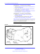
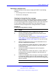
Critical points P11, P13 and P16 form the following:
• contours in Figure 25 "Contours formed by critical points P11,
P13, and P16" (page 56)
•
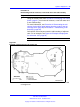
the cell center 1C5 in Figure 26 "Cell center 1C5 formed by
critical points P11, P13, and P16" (page 57)
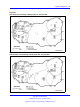
•
a new cell boundary in Figure 27 "Cell boundary 1C5 formed
by critical points P11, P13, and P16" (page 57)
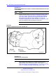
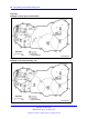
Critical points P11, P12, and P17 form the following:
• contours in Figure 28 "Example of critical point cell
boundaries" (page 58)
• a new boundary based on cell center 1C6 in Figure 29
"Example of cell center boundary 1C6" (page 58)
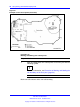
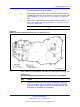
Figure 25 "Contours formed by critical points P11, P13, and P16"
(page 56) shows a floor plan with complete radio coverage. Cell
boundary 1C7 completes the floor plan.
--End--
Figure 25
Contours formed by critical points P11, P13, and P16
Nortel Communication Server 1000
SIP DECT Fundamentals
NN43120-123 02.02 30 March 2010
Copyright © 2008-2010 Nortel Networks. All Rights Reserved.
.