
User's Manual


46 Site planning and hardware deployment
2 Enter the site survey mode on the handset.
For more information, see Procedure 1 “Entering the site survey
mode” (page 41) if you use Deployment Kit 2, or Procedure
149 “Entering the monitor mode” (page 270) if you use an older
Deployment tool.
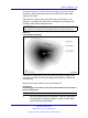
3 Measure the range into the coverage area in a few directions to
determine where a cell center can be located and still be within
range of the critical point.
Listen to the deployment tool handset while moving away from
the basestation. After the RSSI value changes from 7 to 6
(--80dBm to --85dBm), the cell boundary is detected.
For more information about deployment requirements, see“Radio
synchronization” (page 19).
4 Mark the cell boundary on the floor plan with a small x.
5 Repeat step 3 and step 4 until you have sufficient Xs to draw a
thin contour arc through the Xs.
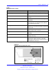
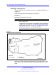
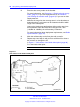
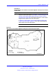
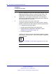
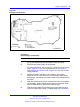
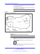
In Figure 17 "Cell contour of the initial critical point" (page 46),
P1 is the initial critical point.
--End--
Figure 17
Cell contour of the initial critical point
Nortel Communication Server 1000
SIP DECT Fundamentals
NN43120-123 02.02 30 March 2010
Copyright © 2008-2010 Nortel Networks. All Rights Reserved.
.