
User's Manual
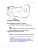
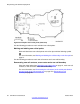
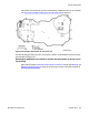
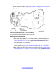
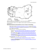

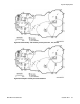
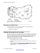
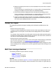
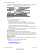

Figure 25: Identify new critical points (P11, P12, P13, P14, P15, P16, P17)
Use the following procedure to mark additional cell boundaries and define the extent of the
coverage area.
Demarcate additional cell boundaries to cover all areas of the building
Repeat the procedures Identifying critical points on the floor on page
45 to
Marking
and labeling new critical points on page 52
as necessary to mark new cell boundaries
at the middle of the building.
Critical points P11, P13 and P16 form the following:
• contours in
Figure 26: Contours formed by critical points P11, P13, and P16 on
page
56
• the cell center 1C5 in
Figure 27: Cell center 1C5 formed by critical points P11,
P13, and P16 on page 56
• a new cell boundary in Figure 28: Cell boundary 1C5 formed by critical points P11,
P13, and P16 on page 57
Critical points P1
1, P12, and P17 form the following:
• contours in
Figure 29: Example of critical point cell boundaries on page 57
•
a new boundary based on cell center 1C6 in
Figure 30: Example of cell center
boundary 1C6 on page 58
System deployment
SIP DECT Fundamentals October 2012 55