
User's Manual
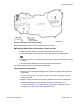
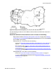

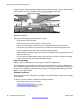

the other end of the building. In Figure 24: Example of deployment for cells 1C3 and
1C4 on page 54
, new cells are formed around cell centers IC3 and IC4.
Figure 24: Example of deployment for cells 1C3 and 1C4
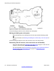
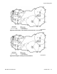
Use the following procedure to identify new critical points.
Identifying new critical points
1.
Mark critical points adjacent to a critical point and on the opposite side of the cell
boundary area. (critical point = P11 in
Figure 25: Identify new critical points (P11,
P12, P13, P14, P15, P16, P17) on page 55
, where cell boundary area = IC2),
The critical points must be as follows.
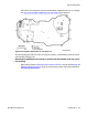
2. Mark critical points inside of where the cell boundary meets the outside wall (P12,
P13, P14, and P15 in
Figure 25: Identify new critical points (P11, P12, P13, P14,
P15, P16, P17) on page 55
, and
3. Mark critical points where cell boundaries meet (P16 and P17 in
Figure 25: Identify
new critical points (P11, P12, P13, P14, P15, P16, P17) on page
55.
Site planning and hardware deployment
54 SIP DECT Fundamentals October 2012
Comments? infodev@avaya.com