SIP DECT Fundamentals Avaya Communication Server 1000 7.5 NN43120-123, Standard 04.
© 2010 Avaya Inc. All Rights Reserved. Notice While reasonable efforts have been made to ensure that the information in this document is complete and accurate at the time of printing, Avaya assumes no liability for any errors. Avaya reserves the right to make changes and corrections to the information in this document without the obligation to notify any person or organization of such changes.
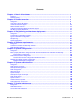
Contents Chapter 1: New in this release........................................................................................... 7 Features.................................................................................................................................................... 7 Revision History........................................................................................................................................ 7 Chapter 2: Product overview......................................
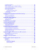
720 DAP LED indications........................................................................................................................ 149 DAP firmware update................................................................................................................................ 150 Remove and replace a DAP (if a new DAP is available).......................................................................... 151 Remove and replace a DAP (if a new DAP is not available)........................
Feature configuration................................................................................................................................ 249 Messaging........................................................................................................................................ 249 Contacts........................................................................................................................................... 250 Settings................................................
SIP DECT Fundamentals October 2012
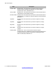
Chapter 1: New in this release The following sections describe what’s new in this document for DECT Release 5.2 and Avaya Communication Server 1000 Release 7.5. • Features on page 7 • Revision History on page 7 Features DECT Release 5.20.091 for Communication Server 1000 Release 7.5 introduces the following: • additional information about G.729 codec • new Messaging and Location Service Revision History Date Description October 2012 Standard 04.06.
New in this release Date Description October 2009 Standard 02.01. This document is up-issued to reflect changes in technical content stemming from SIP DECT 4.2, and to support Communication Server 1000 Release 6.0. January 2009 Standard 01.07. This document is up-issued for Communication Server 1000 Release 5.5 with editorial changes. December 2008 Standard 01.06. This document is up-issued for Communication Server 1000 Release 5.5, in response to change requests for content related to SIP DECT 4.1.
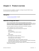
Chapter 2: Product overview This section describes the capabilities, configuration, and design of Avaya SIP DECT for Avaya Communication Server 1000 (Avaya CS 1000). Navigation • Overview of Avaya SIP DECT on page 9 Overview of Avaya SIP DECT You can use Avaya Session Initiation Protocol (SIP) Digital Enhanced Cordless Telecommunications (DECT) to move without restriction about your work site while conducting telephone conversations, using wireless handsets.
Product overview The following software releases are required for the main system components: • Call Server, Release 7.5 or later • SIP Line Gateway application, Release 7.5 or later • DAP software 4910b524.dwl or later • DAP controller 5.2 or later (PC software) You can connect IP Deskphones to the TLAN, and you can connect TDM telephones to the Call Server, Voice Gateway Media Cards, and other required cards in the Call Server.
Overview of Avaya SIP DECT Figure 1: SIP DECT configuration You can install the DHCP or TFTP services, DECT Messenger, and DAP controller on a single server or PC. However, you can also install them on separate servers to enhance performance or facilitate administration.
Product overview Universal extension support DECT Handsets subscribed on DAPs are external to CS 1000. The CS 1000 does not control the state of DECT Handsets. Therefore, the CS 1000 • cannot detect individual key presses on DECT Handsets • cannot control cadences on DECT Handsets • cannot control the DECT Handset display content A DECT Handset subscribed on a DAP cannot use the same range of features available to analog, digital, or UNIStim IP Deskphones on the CS 1000.
DECT Handset features • Calling Line ID (CLID) and Calling Party Name Display (CPND) for simple calls not involving call transfer • CLID and CPND for an internal line (digital or IP phone with display) calling to or receiving a call from a DECT Handset • Sending DTMF tones through the established connection to interact with the called line (party), for example, to work with CallPilot • Support for a voice mailbox on CallPilot and Message Waiting Indication (MWI) • Call Forward No Answer • Call Forward By T
Product overview • Transfer a call to another DN - To perform a Blind Transfer, place the current call on hold, call the required DN, and immediately release from the call. - To perform a Consultative Transfer, place the current call on hold, call the required DN, wait for the answer, and release the call after the DN answers. • Press digit keys on the Handset during an established call to transmit DTMF tones to the other party on the call. • Initiate a three-way call.
SIP DECT capacity limitations A user can call the CallPilot system from a DECT Handset and log on to the voice mailbox with the corresponding DN and password. The user can then use the voice menus of the system as usual. Note: If a voice mail number contains a login (DN) and password for accessing the mailbox, then the 4027, 4070 and 4075 DECT Handsets send digits to the voice mail system at a rate of 40 msec (for RTP stream only).
Product overview Consider the following additional capacity limitations based on the CS 1000 configuration characteristics. • The number of available UEXTs is limited by the number of available virtual Telephone Numbers (TN) in the system. • The number of DNs available for DECT Handsets depends on the configured dialing plan and the availability of the Directory Number Expansion (DNXP) package 150. 16 SIP DECT Fundamentals October 2012 Comments? infodev@avaya.
Chapter 3: Site planning and hardware deployment Navigation • Components of SIP DECT systems on page 17 • Deployment requirements on page 19 • Types of SIP DECT configuration on page 28 • Site planning on page 33 • System deployment on page 40 Components of SIP DECT systems This section contains information about the following topics.
Site planning and hardware deployment For more information about CS 1000 installation, see Avaya Communication Server 1000E Installation and Commissioning, NN43041-310. PC (DAP controller) Minimum specifications for the DAP controller PC are as follows. • 2.4 GHz CPU • 512 MB RAM • CD-ROM drive • 1GB free hard disk space DECT Access Points Four models of DECT Access Points (DAP) are currently available for Avaya SIP DECT: C4710 and C4710E, 4720 and 4720E.
Components of SIP DECT systems Ensure that the DAPs are installed according to the location recommendations. For more information, see Deployment requirements on page 19. Deployment requirements This section describes SIP DECT deployment requirements. Navigation • Radio synchronization on page 19 • IP network configuration on page 23 • Location requirements on page 26 Radio synchronization The radio network structure supports seamless handover of existing calls.
Site planning and hardware deployment Figure 2: DAP radio signal synchronization Due to the cellular structure of a DECT radio network, overlap exists in the cells with sufficient voice quality. The wider cell limit around the DAP therefore has some overlap with the other cell and reaches to the radio of the other cell. Consequently, the DAPs of the overlapping cells exchange radio signals. These radio signals are weak relative the signal needed by the handsets, but are strong enough for synchronization.
Components of SIP DECT systems one or more voice calls occur on the DAP, one is one a dummy bearer, while the others are voice calls. Synchronization hierarchy If two or more DAPs belong to the same system, the DAPs automatically synchronize using a hierarchical structure. In most cases synchronization is automatic, but if your system has a complex DAP cell structure, you must manually configure synchronization.
Site planning and hardware deployment separating them from the master, the new DAP synchronizes to the DAP with the lowest RPN. Important: After you install SIP DECT, wait at least 15 minutes until you see the results of the automatic synchronization. To make a DAP a synchronization master or to give a DAP a higher position in the synchronization structure, you can manually assign a lower RPN number to a DAP. You can manually assign RPNs using the DAP Manager Web interface.
Components of SIP DECT systems Figure 4: Signal strength considerations • An open area has more than sufficient signal strength for synchronization. The expected level at the double distance is --78 dBm. The required level is --80 dBm to --85 dBm. This leaves a safely margin of 2 to 7 dB. • Obstructions between the DAPs can introduce loss. Also, many objects cause reflections that let the signal reach the DAPs through other path with sufficient signal strength.
Site planning and hardware deployment Ethernet requirements The following items describe the Ethernet requirements. • The IP network must offer a Quality of Service (QoS) that is sufficient to support the SIP DECT Voice over IP. • The IP network must support transparent IP multicast between all DAPs and the DAP controller. • Connect only one DAP to one IP Switch port. • DAP supports full duplex and supports autonegotiation if DAP is connected to a port on an Ethernet Switch.
Components of SIP DECT systems server. The DAP then downloads the configuration files from the TFTP server. The TFTP server often runs on the DAP controller or manager PC. • The DHCP server (optional) sends the address of the DNS server to the DAP. The DAP does not support Domain Name Resolution. • The DAP controller or manager requires a fixed IP address. The DAPs retrieve this fixed IP address from the configuration file that the DAP loads from the TFTP server.
Site planning and hardware deployment current connection). This DAP issues a multicast on the network to determine on which DAP the voice connection exists. The DAP, with the existing voice connection, responds and then the connection can be redirected from the DAP with the existing voice connection to the new DAP. • Synchronization between DAPs You must configure multicast before synchronization can occur between DAPs in the SIP DECT system.
Components of SIP DECT systems DAP power configuration The C4710 and C4710E DAPs are powered using one of the following methods: • Locally, using an RJ-11 connector. The AC voltage must be 40V (+ or --10 percent). Use an AC adaptor that provides at least 10 Watts. For part numbers of available AC adaptors, see Table 1: Part numbers on page 27.
Site planning and hardware deployment Figure 5: Color Schemes for Wires in Category 5 Ethernet Cabling Types of SIP DECT configuration You can implement SIP DECT in various system configurations to accommodate your needs.
Types of SIP DECT configuration seamless handover between all DAPs. For an illustration of a simple SIP DECT configuration, see Figure 6: Simple SIP DECT network configuration on page 29. Figure 6: Simple SIP DECT network configuration Routed Head Quarter configuration: Routed Head Quarter Configuration is used for a Large Campus network that is split into several subnets.
Site planning and hardware deployment Figure 7: SIP DECT configuration Routed Head Quarter In Routed Head Quarter Configuration, the network settings must comply with the following requirements: • The network must support Quality of Service (QoS) and IP connectivity throughout the Campus. • Routers must support IP multicast routing. • The IP multicast address for SIP DECT must be the same in all subnets. • Multicast Time to live (TTL) must be greater than 1.
Types of SIP DECT configuration an illustration of a Branch Office Configuration, see Figure 8: Branch Office Configuration on page 31. Figure 8: Branch Office Configuration For Branch Office Configuration, network settings must comply with the following requirements: • The network between Branch Offices and Call Server must support QoS. • Branch Offices must be in separate subnets (IP router(s) needed).
Site planning and hardware deployment Figure 9: Routed Head Quarter Configuration with Branch Office In Routed Head Quarter Configuration with Branch Office the network settings must comply with the requirements for Routed Head Quarter configuration (for the network settings within Routed Head Quarter) and with the requirements for Branch Office configurations (for the network settings between Branch Offices, including the Branch Office with Routed Head Quarter).
Site planning • All visitor UEXT SIPL clients above the maximum licenses number are deleted on sysload. • All visitor UEXT SIPL clients are deleted on sysload if the MSMN package is restricted. • Overlay 20 does not print the VSIT and HMDN lines in reports. • − The visitor UEXT SIPL client cannot move to the new location where the package and license limits exist (Set Relocation feature).
Site planning and hardware deployment • Sensitive electronic equipment Check whether sensitive electronic equipment is present, for example, laboratory or medical equipment. Although the transmitted power of the DAPs is low (about 250 mW), it can interfere with some sensitive electronic equipment. • Traffic information Gather information about user density, amount of traffic, and whether redundancy is required.
Site planning Figure 10: Coverage and speech quality in an open environment. Be aware that DECT is a digital communication system. It incorporates a “transmission errors hiding” system. This means that it tries to hide the transmission errors. The results of this mechanism are as follows: • A small incidental transmission error is not noticeable in speech. • A minor transmission error causes audible clicks during speech. • A major transmission error causes the loss of speech.
Site planning and hardware deployment Any sounds produced by a lower quality level noticed by the system users, because these environments are usually quiet or produce less background noise. • Satisfactory In less critical areas like basements, stock rooms, and cold stores, the satisfactory quality level is usually accepted because they are noisy environments. In a noisy environment people do not notice an audible click in a conversation, because the environment produces a lot of background noise.
Site planning Material Insertion loss (dB) Glass, metal reinforced grid 10 Glass, metal clad sunguard 10 Wall, indoor, plaster, wood 2 Wall, brick, 10 cm 3.5 Wall concrete, 10 cm 6 Wall concrete, 15 cm 9 Wall concrete, 20 cm, large windows 6 Wall concrete, 40 cm 17 Ceiling, concrete, reinforced, tiles 17-20 With the DECT equipment, the available link budget is 38 dB.
Site planning and hardware deployment Figure 11: DECT range calculation chart The range in the air is 80 m from the DAP, for optimal communication quality. The result of this coverage calculation is a map with possible DAP positions indicated. Use the following DAP ranges as a rough guide for planning the DAP positions: • In the line of sights the DAP has a range of approximately 80 m. • In halls the DAP has a range less than 80 m. • In buildings the DAP has a range of 15 to 40 m.
Site planning • Fire resistant doors. • A wall of steel cabinets, large computer equipment or machinery. • Thick concrete floors. During the site survey, be aware of the following: • Choose a corridor or other large open space, rather than an enclosed area, so that the radio signal passes through as few walls as possible to reach as large an area as possible. • Radio reception inside a vehicle is poor unless the user is close to the DAP.
Site planning and hardware deployment The Erlang value for DAP C4710(E) and C4720(E) (12 radio channels), with blocking probability of 0.5%, is 5.25. Calculate the traffic density using the following formula: One cell has 20 users: five average traffic and 15 low traffic. The load is: (5 x 0.15) + (15 x 0.05) = 1.5 Erlang Therefore, one 12 channel DAP is sufficient for this cell. System deployment This section describes the basics of SIP DECT system deployment.
System deployment Figure 12: Deployment Kit 2 and carrying case The following figures shows the assembled kit.
Site planning and hardware deployment Figure 13: Assembled Deployment Kit 2 and DeTeWe handsets 42 SIP DECT Fundamentals October 2012 Comments? infodev@avaya.
System deployment Figure 14: Deployment Kit 2 basestation Use the following information in conjunction with the DeTeWe User Manual that accompanies the deployment tool. • The two DeTeWe handsets with the kit are subscribed to the basestation and are numbered 13 and 15. To view the assembled basestation and the DeTeWe handsets, see Figure 13: Assembled Deployment Kit 2 and DeTeWe handsets on page 42. • The key on the handset is the Off-Hook key.
Site planning and hardware deployment Indication (RSSI) value of –80 dBm to –85 dBm is used to indicate the cell boundary. For more information, see Signal strength and frame errors on page 22. Re-subscribing a handset To re-subscribe a handset that has de-subscribed in error, perform the following procedure. 1. Long-press the button on the basestation to open the DECT system. 2. On the handset, navigate to Menu > System > Subscription > New. 3.
System deployment Term Traffic table Definition Traffic tables record site traffic information from the floor plan and the customer. The traffic table helps to determine the required number of basestations for each cell. The following figure illustrates some of the preceding terms. Figure 15: Example showing deployment terms Deploying on a single floor Use the information in this section when you are installing SIP DECT on a single floor.
Site planning and hardware deployment A critical point is a place that can be difficult for the radio signal to reach, such as a corner of a room, lifts, and stairwells. Initial critical points are shown in Figure 16: Example of initial critical points on page 46 as: P1, P2, P3, P5, P6 and P7. Figure 16: Example of initial critical points A specific RSSI value on the handset defines the cell boundary range. Links can be made outside the cell boundary but the audio quality of the link is poor.
System deployment Figure 17: Cell boundary terminology Determine a cell boundary for the cell center by placing the deployment tool at the cell center and using the deployment handset to establish the cell boundary. Use the following procedure to mark the cell contour based on the most distant point. Demarcating the cell contour for the critical point farthest from the center of the full coverage area 1. Set up the deployment tool basestation.
Site planning and hardware deployment In Figure 18: Cell contour of the initial critical point on page 48, P1 is the initial critical point. Figure 18: Cell contour of the initial critical point Demarcating the cell contour of the closest adjacent critical point to the first critical point.
System deployment In Figure 19: Cell contour of the closest adjacent critical point to the initial critical point on page 49, P2 is the closest adjacent critical point to the first critical point. Figure 19: Cell contour of the closest adjacent critical point to the initial critical point Use the following procedure to locate the cell center. Locating the cell center 1. Place the deployment tool at one critical point and then use the deployment handset to obtain a change in audio quality.
Site planning and hardware deployment In Figure 20: Example of a cell center on page 50, IC1 is a cell center. Figure 20: Example of a cell center Use the following procedure to mark the cell boundary. Demarcating a cell boundary 1. Set up the deployment tool basestation at the cell center. 2. Enter the site survey mode on the handset.
System deployment Figure 21: Example of a cell center boundary Use the following procedure to mark and label the cell boundary. Marking and labeling the cell boundary on the floor plan 1. Mark each office within the cell that is isolated from the office area. 2. Label subsequent critical points on the floor plan with the following symbol. 3. Mark the cell contour on the floor plan by tracing a contour line through the Xs with a marker. 4. Trace the cell boundaries and cell centers with colored markers.
Site planning and hardware deployment Figure 22: Example of new critical points (P8 and P9) Use the following procedure to mark and label new critical points. Marking and labeling new critical points Mark and label these new critical points on the floor plan with the following symbol. For more information, see Marking and labeling the cell boundary on the floor plan on page 51. Use the following procedure to mark new cell contours and a new cell boundary.
System deployment Cell contour arcs must pass near the cell boundary of adjacent cells. For an example, see Figure 23: Example of deployment for cell center 1C2 on page 53. Figure 23: Example of deployment for cell center 1C2 Use the following procedure to mark cell contours, centers, and boundaries at the far end of the intended coverage area.
Site planning and hardware deployment the other end of the building. In Figure 24: Example of deployment for cells 1C3 and 1C4 on page 54, new cells are formed around cell centers IC3 and IC4. Figure 24: Example of deployment for cells 1C3 and 1C4 Use the following procedure to identify new critical points. Identifying new critical points 1. Mark critical points adjacent to a critical point and on the opposite side of the cell boundary area.
System deployment Figure 25: Identify new critical points (P11, P12, P13, P14, P15, P16, P17) Use the following procedure to mark additional cell boundaries and define the extent of the coverage area. Demarcate additional cell boundaries to cover all areas of the building Repeat the procedures Identifying critical points on the floor on page 45 to Marking and labeling new critical points on page 52 as necessary to mark new cell boundaries at the middle of the building.
Site planning and hardware deployment Figure 26: Contours formed by critical points P11, P13, and P16 on page 56 shows a floor plan with complete radio coverage. Cell boundary 1C7 completes the floor plan. Figure 26: Contours formed by critical points P11, P13, and P16 Figure 27: Cell center 1C5 formed by critical points P11, P13, and P16 56 SIP DECT Fundamentals October 2012 Comments? infodev@avaya.
System deployment Figure 28: Cell boundary 1C5 formed by critical points P11, P13, and P16 Figure 29: Example of critical point cell boundaries SIP DECT Fundamentals October 2012 57
Site planning and hardware deployment Figure 30: Example of cell center boundary 1C6 Deploying on multiple floors Use the information in this section to deploy SIP DECT in the following situations. • The coverage area is on more than one floor. • The floors are not adjacent. Checking for through-the-floor coverage The first step in covering a multi-floor building is to assess the availability of through-the-floor coverage. In buildings mainly constructed of wood, you can use through-the-floor coverage.
System deployment 3. Measure the deployment contour as if the basestation was on this floor, instead of the floor below. If only a small area is covered (less than a 10 metre radius), no through-the-floor coverage is available on the floor above an installed basestation. 4. Go to the floor below the deployment tool and repeat the preceding process. If only a small area is covered (less than a 10 metre radius), no through-the-floor coverage is available on the floor below an installed basestation. 5.
Site planning and hardware deployment to plan an atrium. No precise steps to follow when you deploy an atrium, but you must consider several points. For more information, see Unusual conditions on page 60. Figure 31: An atrium Consider the following points to deploy in an atrium: • Plan atriums to the full height. • Plan an atrium as one full size room, not floor by floor. • Place cell centers within an atrium only if you intend for them to cover the atrium.
System deployment Cell centers are too close If you deploy cell centers less than 10 metres apart, the handsets can initiate unnecessary handover. Unnecessary handover results in excessive internal messaging and degraded speech quality. Cell centers are too far apart If you deploy cell centers too far apart, the edge of a cell does not overlap the coverage from another cell. Cell centers must be within the edge of other cell centers to provide satisfactory overlap.
Site planning and hardware deployment Figure 32: Locating redundant cells Reengineer cells for high traffic areas To accommodate the demand in high traffic areas, follow The cell reengineering process on page 62. Traffic volume The deployment process ensures coverage throughout the service area. It does not, however, take into account the effect of traffic. To support the volume of telephone calls in cells that carry high traffic, you must increase the number of cells deployed.
System deployment • Calculating the data for all remaining cells on page 67 • Creating a table to document telephone types in a cell on page 67 • Determining cell reengineering on page 68 Estimating traffic within a cell To adjust the number of users supported by the system, you can modify the deployment procedures you followed in Deploying on a single floor on page 45 or Deploying on multiple floors on page 58.
Site planning and hardware deployment Mark the cell areas on the floor plan, one area for each cell, and split cell overlap areas in half, as shown in Figure 33: Example of dividing the coverage area and recording offices on page 63 as heavy dotted lines. 2. Count the number of user offices in each cell area. 3. Record the number of user offices on the floor plan in each cell area. Creating an estimate table Use the following table to estimate the number of handset users for each cell.
System deployment Calculating the number of users inside the cell with an office 1. Estimate the number of users in the first cell with an office. Use the formula: (users with an office in the cell × 0.7) 2. Enter the result in the row Users inside the cell with an office. In the example in Figure 33: Example of dividing the coverage area and recording offices on page 63, 12 users in cell 1C1 spend 70 percent of their time in their offices (12 × 0.7 = 8.4) .
Site planning and hardware deployment Calculating the number of users without an office Table 8: Example of the table third row calculation Estimate for: 1C1 1C2 1C3 1C4 1C5 1C6 1C7 Users inside the cell with 8.4 an office Users with an office 3.2 outside of a cell who walk into the cell Users without an office 0 Users in a cell Calculating the number of users without an office 1. Calculate the estimate for users in the first cell without an office. Use the following formula: 2.
System deployment 8.4 + 3.2 + 0 = 11.6. Calculating the data for all remaining cells Table 10: Example of a completed estimate table Estimate for: 1C1 1C2 1C3 1C4 1C5 1C6 1C7 Users inside the cell with an office 8.4 0.7 21.0 14.7 0.7 4.9 2.1 Users with an office outside of a cell who walk into the cell 3.2 3.7 2.3 2.7 3.7 3.4 3.6 0 0 0 0 0 0 0 11.6 4.4 23.3 17.7 4.4 8.3 5.7 Users without an office Users in a cell Calculating the data for all remaining cells 1.
Site planning and hardware deployment Use the information in this table to determine the number of cells that require reengineering. Determining cell reengineering Table 12: Example of a completed estimate table Estimate for: 1C1 1C2 1C3 1C4 1C5 1C6 1C7 Users inside the cell with an office 8.4 0.7 21.0 14.7 0.7 4.9 2.1 Users with an office outside of a cell who walk into the cell 3.2 3.7 2.3 2.7 3.7 3.4 3.6 0 0 0 0 0 0 0 11.6 4.4 23.3 17.7 4.4 8.3 5.
System deployment 3. Locate the telephone type column in Table 12: Example of a completed estimate table on page 68. In the example, H&W is the users with both a handset and a wired telephone. 4. Find the handset estimate range in Table 14: Cell reengineering on page 68. In the example, 11.6 falls within the From 0 up to 20 category. 5. Determine if a cell requires division or uses a 12-channel basestation. In the example From 0 up to 20, division is not required. 6.
Site planning and hardware deployment 70 Estimated number of handsets for users without wired telephones Adjusted estimated number of handsets for each cell 3 5 4 7 5 9 6 11 7 12 8 14 9 16 10 18 11 20 12 22 13 24 14 25 15 27 16 29 17 31 18 34 19 36 20 38 21 40 22 42 23 44 24 46 25 48 26 49 27 50 28 53 29 55 30 57 31 60 32 62 SIP DECT Fundamentals October 2012 Comments? infodev@avaya.
System deployment Estimated number of handsets for users without wired telephones Adjusted estimated number of handsets for each cell 33 64 34 66 35 69 36 71 37 73 38 76 39 78 40 80 Adjusting for users without wired telephones 1. Count the number of user offices with handsets and wired telephones (H&W), and record the number. 2. Count the number of user offices that have only wireless handsets, (H). 3.
Site planning and hardware deployment Important: If you install two DAPs close to each other for extra traffic density, ensure the distance between the DAPs is always more than one meter and preferably more than 5 meters. Figure 34: Example of a subdivided cell In Figure 34: Example of a subdivided cell on page 72, cell 1C1 has 140 handset users and cell 1C2 has 100 handset users.
System deployment 7. Take the deployment tool to the locations calculated on the floor plan. Ensure that there is a location that meets the requirements in Deployment requirements on page 19. 8. Ensure the new cells have complete coverage. 9. Use the deployment handset to check coverage. 10. Repeat the anticipated handsets for each cell calculation to ensure that each smaller cell provides appropriate traffic coverage to the users in the area.
Site planning and hardware deployment 74 SIP DECT Fundamentals October 2012 Comments? infodev@avaya.
Chapter 4: Software requirements Navigation • Call Server and SIP Line Gateway software on page 75 • DAP controller software on page 75 Call Server and SIP Line Gateway software For information about the CS 1000E Call Server, see Avaya Communication Server 1000E Installation and Commissioning, NN43041-310. For more information about SIP Line Gateway application installation, see Avaya SIP Line Fundamentals, NN43001-508.
Software requirements If a firewall is installed on your DAP Controller PC, ensure the firewall does not block the ports used for various services. For information, see Firewall protection on page 76. • Internet Explorer 6.0 or later • MS .
DAP controller software information about Microsoft Windows 2003 DHCP and TFTP server installation and configuration, see DHCP and TFTP servers. The DAP controller software includes DHCP and TFTP servers that you can configure from the IP DECT Configurator. For more information about built-in DHCP and TFTP servers, see Built-in DHCP and TFTP servers on page 86. You can create a DAP configuration without DHCP or TFTP; however DHCP and TFTP must be available to program or reprogram DAPs.
Software requirements The Components window appears. 5. Select the Dynamic Host Configuration Protocol (DHCP) check box. 6. Click OK. 7. Click Next. 8. Insert the Windows CD-ROM as prompted. 9. Finish the procedure using the instructions in the dialog box. 10. Close the Add/Remove Programs window and close the Control panel window. Configuring the Settings for SIP DECT 1. Start the DHCP manager:Start > Programs > Administrative Tools > DHCP. The DHCP Administration Tools window appears.
DAP controller software 2. Select the active DHCP server and create a new scope: Action > New Scope. The New Scope Wizard starts. 3. Click Next in the wizard dialog box. 4. Enter a name and description for the new scope; for example, SIP DECT. 5. Click Next in the naming dialog box see the IP address range. The window New Scope Wizard—IP address range appears.
Software requirements 6. Define a range of IP addresses for the DAPs used; for example, 192.168.100.200 to 210. 7. Define the associated subnet mask; for example, 255.255.255.0. 8. Click Next. The New Scope Wizard—Exclusion of an IP address range window appears. 9. Enter the Start IP address and End IP address values to exclude; for example, the IP addresses of DHCP server and the TFTP server.
DAP controller software 14. Select No, and click Finish. The newly created scope appears with a new line called Scope Options. 15. Right-click Scope Options, and select Configure Options. The Scope Options page appears.
Software requirements 16. Select the Option 066 check box, and enter the IP address of the TFTP server; for example, 192.168.100.10. This can be the IP address of your DAP controller or manager, if the TFTP server is running there. 17. Check Option 067 for the boot file name. Enter dapcfg.txt. 18. Select the Option 3 check box, and enter the Router or Default Gateway IP address (for example, 192.168.100.1), and click Add. 82 SIP DECT Fundamentals October 2012 Comments? infodev@avaya.
DAP controller software 19. Click Apply to save the changes and OK to close the dialog box. 20. Right-click Scope, and select Activate. Now your DHCP server is configured correctly. 21. Close the DHCP window. TFTP server Many types of TFTP servers are available, including shareware and freeware. A TFTP server must handle several accesses at the same time, because several accesses occur at the same time, when the DAPs start simultaneously.
Software requirements Installing the TFTP server 1. If you have Windows 2003, go to Start > Control Panel in Windows. 2. Open Add/Remove Programs. 3. Click on the Add/Remove Windows Components. The Windows Components Wizard window appears. 4. In the Components window, select the Remote Installation Services check box. 5. Click Next. 6. Insert the Windows 2003 CD-ROM as prompted. 7. Follow the instructions in the dialog box to complete the procedure. 8.
DAP controller software The Services window appears. 4. Select Trivial FTP Deamon. 5. Right-click the Trivial FTP Deamon , and then select Start. 6. Right-click the Trivial FTP Deamon, and then select Properties. 7. Change the Startup Type setting to Automatic. 8. After you install TFTP on your PC , a folder named tftpdroot is created. Important: If you run Windows 2003, you must create the TFTP folder on drive C:, as shown in the following figure.
Software requirements Built-in DHCP and TFTP servers The DAP controller software has a built-in DHCP and TFTP server. The built-in DHCP and TFTP servers do not require manual configuration, because the IP DECT Configurator performs the configuration. Important: You can configure a Built-in DHCP and TFTP server only after you install the IP DECT Configurator. For more information, see DAP Controller on page 90. Built-in DHCP server The DAP controller software has a built-in DHCP server.
DAP controller software You can configure built-in DHCP server using the Network Settings window of IP DECT Configurator. Prerequisites If you are configuring a new system, perform the following procedures before you configure the built-in DHCP server. • Starting the IP DECT Configurator on page 94 • Adding a new system using the IP DECT Configurator on page 94 Configuring the built-in DHCP server using the IP DECT Configurator Network Settings Window 1.
Software requirements Configuration without DHCP or TFTP Important: DAP configuration without DHCP or TFTP requires DHCP and TFTP to be temporarily available to program or reprogram DAPs. You can perform DAP configuration without DHCP or TFTP only after you install the IP DECT Configurator. For more information, see DAP Controller on page 90. You can install the DAPs in an IP environment without a DHCP server, a TFTP server, or neither.
DAP controller software 4. Click the Advanced tab, and select Both for Assign IP addresses dynamically to clients of and Unlimited for Lease duration for OOTP clients. 5. Click OK to save changes.
Software requirements DAP configuration without DHCP or TFTP servers You can perform DAP configuration without DHCP or TFTP servers using the Network Settings window of the IP DECT Configurator. Configure a DAP to store IP address and configuration data. Storing IP address and configuration data on a DAP 1. Start the IP DECT Configurator and select Modify the system. 2. Select the system to modify. 3. In the Network settings pane select the Boot Options tab. 4. Select the DAP Boot Options check box. 5.
DAP controller software Depending on the directory structure on the CD-ROM, the setup.exe file is on Disk 1. The InstallShield Wizard appears. This window remains visible while you install the DAP controller components and gives you information about the installation progress. After the PC restarts, it automatically continues with the DAP controller installation. The DAP controller - InstallShield Wizard page appears. 2.
Software requirements The Ready to install the program page appears. 9. Click Install to start the installation. The system installs the software. The InstallShield Wizard Completed page appears when the installation is complete. 10. Click Finish. The IP DECT Configurator starts automatically, so that you can configure your SIP DECT system. 92 SIP DECT Fundamentals October 2012 Comments? infodev@avaya.
Chapter 5: System configuration Traditional Digital Enhanced Cordless Telecommunications (DECT) is an application on the system that allows digital wireless capabilities. With DECT, users can move around their work sites while answering a call, making a call, continuing a call, or transferring a call.
System configuration Configuration using IP DECT Configurator Use the IP DECT Configurator tool to create configuration files for the DAP controller and DAPs. The IP DECT Configurator is installed and starts automatically when you install the DAP controller software. You can also start the IP DECT Configurator by using the shortcut to the IP DECT Configurator tool under the Start menu at Programs > DAP controller > DAP Applications.
Basic (simple) SIP DECT configuration with Communication Server 1000 SIP Line Gateway 4. In the General Settings window, enter the path to the firmware, the DAP package file; for example, C:\tftpdroot\4910b524.dwl. 5. Click Apply. Configuring IP Settings 1. On the Settings pane, click IP Settings. The IP Settings page appears. 2. In DAP Controller IP Configuration tab Enter the DAP controller Configuration: DC IP address, which is the IP address of the PC where your DAP controller is installed.
System configuration 3. In TFTP Settings tab select the Run TFTP server on this PC check box, and choose one of the following options: • If you use a Microsoft Windows TFTP server, select Windows TFTP server on this PC. OR • If you use a built-in TFTP server, select 3com TFTP server on this PC. 4. in DHCP Settings tab configure the DHCP server. • If you use a Microsoft Windows DHCP server, click Apply. OR • If you use a built-in DHCP server, see Built-in DHCP server on page 86.
Basic (simple) SIP DECT configuration with Communication Server 1000 SIP Line Gateway The SIP Settings window appears. Figure 35: SIP settings 2. In General Settings tab In the SIP Domain field, enter the domain name. The SIP domain you enter here must be the same as the SIP domain name you enter as the domain in SIP LINE Gateway, in SIP Line Gateway configuration on page 106. 3. Click Proxy IP to use SIP Line Gateway as Registrar. This option is not available if your system uses Multiple Gatekeepers. 4.
System configuration the user password sent by SIP DECT to the SIP Line registrar contains the additional symbols and the handset DN. When you add a UEXT on the Call Server, ensure that you enter the correct user name at the SIPU prompt (SIP DECT handset DN) and password at the SCPW prompt (DN or combination of entered symbols and DN) For example, if you enter %s for user and 12%s34 for password, the DAP attempts to register DECT handset 5001 as user 5001@domain with password 12500134.
Basic (simple) SIP DECT configuration with Communication Server 1000 SIP Line Gateway Note: SIP DECT does not support a payload size of 10 ms. g. Select the check box for Call_waiting_indication and enter the text that will be displayed on the screen of the handset for second incoming call. h. select the check box for 404 and enter the text that will be displayed on the screen of the handset if a called user is not found. i.
System configuration package. For more information, see G.729 daughterboard and DAP wall mounting on page 175 • The G.729 codec is primarily intended for inter-DAP voice transmission. The DAP determines if calls between SIP DECT handsets and IP-based endpoints use G.711 or G.729, regardless of zone configuration (Best Bandwidth or Best Quality) on CS 1000. • The options preferred use of G.729 and only use of G.729 in DAP Controller are not supported. 4. Click Apply. 5. Click Save.
Basic (simple) SIP DECT configuration with Communication Server 1000 SIP Line Gateway 8. Select the Email Settings tab 9. Enter a value next to SMTP Server with the DNS name or the IP address of your SMTP mail server. Email messages can be sent automatically if a DAP fails or if the channel occupation threshold is exceeded for more than a specified number of seconds.
System configuration tries to send an archive and it takes longer than the time specified here, the attempt is terminated. 22. If you check Use client resolution, you can no longer scroll through lists; instead, the available information is broken into pages. You can select pages using tabs. If this box is unchecked, you can scroll through the information using the scroll bar. The information is still separated into pages, but each page contains more information. 23. Click Apply.
Basic (simple) SIP DECT configuration with Communication Server 1000 SIP Line Gateway time expires, IP DECT Configurator will be closed, but all services will be up and running. To stop the timer open any configuration tab. Enabling or re-enabling the DAPs To enable or re-enable the DAPs, start the DAPs. DAP manager configuration The following procedures are described in this section.
System configuration In the DAP manager task area, choose one of the following options: • Reboot—Select this option to restart a selected DAP. • Reboot All—Select this option to restart all DAPs in the list. • Delete—Select this option to remove a DAP from the list. The DAP takes a few minutes to restart. 3. Confirm the DAP is active by checking the status of the device under the Working column. Active DAPs have Yes in this column. Adding number range Follow this procedure to add a Number Range.
Basic (simple) SIP DECT configuration with Communication Server 1000 SIP Line Gateway 2. Select the required available extension number or numbers. If the required number is not visible, select another page. The page number appears in the top and bottom rows of the subscriptions table. 3. Click Enable. Important: If you plan to create a multiple-site configuration, use the option Enable for MultiSite instead of Enable.
System configuration The DN appears on the handset display. The status of the subscription record changes from Enabled to Subscribed. For information, see Subscription management on page 123. SIP Line Gateway configuration There are no specific SIP DECT configuration requirements for SIP Line. For information about installing and configuring SIP Line Gateway, see Avaya SIP Line Fundamentals, NN43001-508.
Basic (simple) SIP DECT configuration with Communication Server 1000 SIP Line Gateway If you plan to configure Microsoft Office Communicator for your SIP DECT handset, you must add the required settings to the UEXT block (AST 0; CLS T87A).
System configuration Branch Office configuration supports seamless handover within each branch office, but not between sites. Support is unavailable for roaming between branch offices. To configure Branch Office, see Basic (simple) SIP DECT configuration with Communication Server 1000 SIP Line Gateway on page 93. Use the information in this section when you require information about Branch Office configuration. Use the following procedure to select a Branch Office configuration.
Routed Head Quarter configuration 4. Configure each branch office by entering the following parameters: • Subnet - the first address in the subnet range. For instance, 192.168.32.0. • Subnet mask - mask to specify the subnet boundaries. • RPN range - lowest RPN and highest RPN in this Branch Office. • Subnet name – any name used to identify the Branch Office. • Time Offset - time zone for the current subnet (branch office). 5.
System configuration addresses of the DAP or DAPs using this subnet mask. If the IP addresses are in various subnets according to this mask, the DAP or DAPs are supposed to be in a branch office. If the IP addresses are in the same aggregated subnet according to this mask, the system assumes that the IP addresses are in the same subnet. The term aggregated means that the subnet consists of smaller subnets connected over a router, but according to the subnet mask, all behave as one subnet.
Routed Head Quarter configuration If you were referred to this procedure from Configuring System Settings on page 96, click Apply, and continue configuring the SIP DECT system using Configuring SIP Settings on page 96. OR Go to step 7. 7. Click Save System and deactivate the system. 8. Ensure that DHCP and TFTP servers are configured properly, so that DAPs can start in all subnets. 9. Activate the system and restart all DAPs. 10.
System configuration each isolated site (branch office), but not between sites. Support is unavailable for roaming between branch offices. Follow this procedure to configure Routed Head Quarter with Branch Office(s) Choosing system configuration 1. Perform one of the following steps: If you were referred to this procedure from Configuring System Settings on page 96, go to step 3. OR Open the IP DECT Configurator, and click Modify. 2.
Multiple-site mobility network configuration Multiple-site mobility network configuration A multiple-site mobility network makes it possible to use portable DECT handsets on various MCDN nodes with installed SIP DECT systems. It is possible for only one subscription to be in the handset for all SIP DECT systems when you use SARI. In this case SARI on all SIP DECT systems must be the same.
System configuration Important: Configuring SIP DECT systems used for MSMN ensure that you use the same SARI on all of them. For more information, see Configuring DECT Settings on page 99. Call Server Configuration MSDN configuration requirements: 1. Uniform (UDP) or coordinated (CDP) numbering plan must be configured on all sites. 2. All sites must be connected through trunks; Private Network Identifier (PNI) must be the same for all systems. 3.
Multiple-site mobility network configuration 4. Click OK, and then Save in the File Download Page. 5. Enter the name of the file with exported subscriptions, navigate to the folder in which to store the file, and click Save. Importing subscriptions on remote systems 1. Open localhost/cds in your Internet Browser (on DAP controller PC). The DAP manager IP DECT page appears. 2. In the navigation menu, click Pack Up & Go. 3. Click Import. 4.
System configuration Prompt Response Description HMDN xxxx HoMe Directory Number sets the DN as a valid MCDN network DN (for example, DSC+DN or AC+LOC+DN) HMDN available if VSIT = YES CLS CFXA Call Forward All Calls to external DN Allowed (required for MSMN configuration) KEY 0 aaa yyyy, for example, 0 SCR 5010 0 aaa yyyy = Primary UEXT DN • aaa = MCN, MCR, SCN, or SCR • yyyy = primary DN 1 HOT U yyyy, for 1 hot u yyyy = Target DN example, 1 HOT • yyyy = User Agent DN prefix (configured for SIP
Multiple-site mobility network configuration - cls FNA FBA MWA Note: Ensure that message waiting indication is enabled in Customer Data Block (LD 15): IMS must be set to YES; MCI must be present in the OPT prompt (FTR_DATA). Operating the MSMN feature To activate the MSMN feature, perform the following steps: • Turn the handset on within the coverage range of a visited DECT system (Remote Call Forward is activated).
System configuration The SIP Line Gateways in Main Office and Branch Office must have the same configuration values for domain name for SIP Line and the user name and password for each SIP DECT user. The primary proxy in Communication Server 1000 Survivable Branch Office is configured to the Main Office SLG IP address to reduce registration time in normal operation mode when the Main Office is operating correctly.
Multiple-site mobility network configuration Note: You must save the system and restart the DAPs to activate the new configuration. Load Balancing for SIP DECT high capacity Consider the following factors when you plan the interaction between a Communication Server 1000 and SIP DECT and when the anticipated number of DECT handsets in SIP DECT systems is large (greater than 200).
System configuration - The primary proxy for DNs starting with 51 is 192.168.32.172. - The primary proxy for all other DNs is 192.168.32.126 Figure 37: Load balancing configuration • Configuration specifics, behavior, and limitations of SIP DECT load balancing configuration: - SIP Line UEXT is configured with Node ID (NDID prompt in LD 11). This configuration parameter is no longer used for SIP Line trunk designation. - A set of SIP Line trunks must be assigned to every SIP Line Node.
Chapter 6: System administration This chapter contains information about the administration of the Avaya SIP DECT system for Avaya Communication Server 1000 (Avaya CS 1000) .
System administration This DAP manager page is divided into four main panels. 1. Main • Subscriptions Use this section for subscription management. • Access points Use this section to restart DECT Access points and view the configuration data. The numbers between brackets indicate the number of present or working Access Points. • Add number range Use this section to enter the available extension numbers. • Backup (export) Use this section to create a backup of your system.
Subscription management The Task list shows the available tasks for a feature. For example, the feature Subscriptions has the tasks Enable, Disable, Terminate, and Delete Number. 3. Information area Notes or additional information appear in this area. 4. Work space You can enter or view data in the Work area. Subscription management This section describes how to subscribe handsets. Before you can use a handset, you must register the handset and subscribe it to the system.
System administration when it performs each subscribe operation; the PIN appears only when the subscription status is Enabled. You can enable up to 10 extension numbers for subscription at the same time. Important: If you plan to create a multi-site configuration, use the option Enable for multisite instead of Enable. 5. Using the handset you are subscribing, access the System configuration menu, and choose New.
Subscription management 5. Enter the RPN of the required installed DAP. 6. Click OK. The maximum number of subscription records for every DAP is 25. Disable a subscription Follow this procedure to disable a subscription. When you disable a subscription, the system attempts to remove the subscription data from the handset. If the subscription data is removed successfully, the DN is available for use by another handset, and you can register the handset again.
System administration localhost/cds. The DAP manager IP DECTDAP manager IP DECT page appears. 2. Select Subscriptions. The Subscriptions page appears. 3. Select the DN to disable. If the DN you plan to disable is not visible, go to subsequent pages until you find it. The page number appears in the top and bottom rows of the subscriptions table. 4. Click Terminate. The status of the configuring subscription record changes from Subscribed to Free.
Subscription management TheFilters page appears. 4. Click the Filter menu, and choose the required filter type. For an explanation of the various filter types, see Table 19: Filter types on page 127. 5. To disable the Filter, click the Filter and select No Filter from the list. Table 19: Filter types Filter type Description DNR filter Use the DNR filter if a list of subscriptions is long and it is difficult to find certain extension numbers or DNRs.
System administration Filter type Handset type filter Description Use the Handset type status filter to look at the records subscribed on some specific handset type (for example, 4027, 4070, 4075). To activate the filter, select the required handset type. Handset status The Subscriptions window in the DAP manager IP DECT shows three columns indicating the status of a handset. • Status This shows the status of the handset subscription in the DECT system.
DAP management The Registration status indicates the status of the handset in the SIP DECT system. The status is Registered or Absent. - If the Registration status is Registered, the handset is registered in the SIP DECT system and can make calls. - If the Registration status is Absent, the handset is not registered in the SIP DECT system and cannot be used to make calls.
System administration 3. Select the DAP to edit. 4. Click Edit. 5. Enter the new RPN. The RPN must be a hexadecimal two-digit number in the range 000 to 00F. 6. Click OK. Wait until DAP restarts and starts working. Restarting a DAP Follow this procedure to restart a DAP. This can be required if you are upgrading software, or if a DAP is not functioning properly. Restarting a DAP 1. Open Internet Explorer and enter the following URL in the address field: localhost/ cds.
DAP management Important: If you use Reboot to restart a DAP, information about types and software versions of subscribed handsets is lost, and is restored after several hours. You can restore this information immediately using either of the following methods: • Turn the handsets subscribed to the restarted DAP off, and then on again. • Restart all DAPs using the option "Reboot all" in DAP Manager. For information, see Restart all DAPs on page 131.
System administration Add a DN range Follow this procedure to assign a DN range. Assigning a DN range manually 1. Open Internet Explorer and enter the following URL in the address field: localhost/ cds. The DAP manager IP DECT page appears. 2. Click Add Number Range. The Add Number Range page appears. 3. In the From field, enter the first number in the range. If you add a range consisting of one number only, proceed to step 5. 4. In the To field, enter the last number in the range. 5. Click OK.
System backup Import a DN range from a .csv file. Two types of .csv files are supported: • A plain .csv file. The most simple file can be a simple text file stored as CS file. Each extension number must be preceded by two commas (,,) to indicate two empty fields. • A Central Directory .csv file. When you use the Central Directory Access tool with an .xls file, you can convert this xls file to .csv format by using Microsoft Office Excel.
System administration The DAP manager IP DECT page appears. 2. Click Backup. The File Download page appears. 3. Click Save. 4. Select the folder in which to store the backup file. 5. Enter a name for the file. 6. Click Save. The file is saved to the selected location. 7. To restore the system, see Import a system on page 166. Subscription export and import Perform the procedures in this section to transfer subscriptions between SIP DECT systems.
Subscription export and import 3. If you are exporting multi-site subscriptions, select Multi-site subscriptions. 4. Enter the PARI of the remote system. 5. If you are exporting multi-site subscriptions, enter the SARI of the remote system. 6. Click OK. 7. Click Add Number Range. The Add Number Range page appears. 8. In the From field, enter the first number in the range of DNs to which you want to export subscription data. If you are exporting data for one DN only, proceed to step 16. 9.
System administration 13. Using the handset you are subscribing, access the System configuration menu, and choose New system. For information about accessing this menu, and other handset configuration information, see the handset User Guide. 14. If the handset requests a Portable Access Rights Key (PARK) code, enter the PARK code. You can find the PARK code on the left at the bottom of the page.
DAP reboot history The Import page appears. 4. Navigate to the folder where the file to be imported is stored. 5. Select the file to be imported. 6. Click OK. You must also configure the CS 1000 system to which the SIP DECT system is connected. For information, see Call Server Configuration on page 114. DAP reboot history Review the log of DAP restarts. The information available includes data that is not readable; to access unreadable data, contact Avaya support. Reviewing the DAP reboot history 1.
System administration 3. Select Generate and save a new archive file to create a new archive file. OR Save the nightly generated archive file to save a copy of the automatic archive, which is generated at midnight each day. 4. Click OK to go to the File Download page. OR Select the check box next to Send by email to, enter the email address to get the archive for each email, and click OK. You must configure the SMTP server before you use this feature.
Handset firmware update The Firmware Upload service must be running. If the Firmware Upload service is not running, a qualified engineer must first start the service. Follow this procedure to update the handset firmware. Updating the handset firmware 1. Click the menu Handset Firmware Update in the Main Window. The Handset Firmware Update window appears. 2. Click the option Configuration The Configuration window appears. 3.
System administration 6. Ensure the new firmware packet is available on the hard disk. 7. Click the option Define Handset Packages. The Define Handset Packages window appears. 8. In the Select handset packages window, select the handset type. 9. Browse to the new firmware package, for example, 4070_v0133.bin, and click Upload. The firmware file name must be in a specific format, for example, 4027_vXXXX.bin, 4070_vXXXX.bin, or 4075_vXXXX.bin, for which XXXX is the firmware version.
Handset firmware update 13. In the Add handsets window, add the extension number range on which to upgrade firmware. 14. Click OK. 15. Click Update Handsets. A list of the handsets that are ready to update appears. 16. Click Start Update to start the update. The update starts according to the time schedule you defined. The status of the update process appears in the Update handsets window, as shown in the following figure. After the update, the handset continues to use the old firmware packet. 17.
System administration There are two options in restarting the handset. • If the handset is in the charger, the handset automatically restarts. No manual intervention is needed. • If the handset is not in the charger and you want to activate the new software immediately, switch off the handset and switch it on again. After the handset switches over to the new firmware packet, the message “Firmware Update in progress. Do not switch off" appears. 19.
Central Directory access tool Creating an Excel file for the central database 1. Open Microsoft Office Excel. 2. Add three columns as shown in the following figure. Important: It is important to use the column headers DBID, Name, and Extension. The first column contains sequence numbers and each must be unique. 3. Add as many rows as entries. If the number of entries in the spreadsheet is small (about 10), then you can see some of the entries more than once on the handset display while scrolling the list.
System administration 4. Run the setup.exe file, and perform one of the following steps: If Microsoft Office Access database engine is available on your PC, the Central Director Access Startup window appears. Proceed to step 5. OR If Microsoft Office Access database engine is not available, you are prompted to install Microsoft Office Access database engine 2007. If you use the Microsoft Windows 2000 Server, you are prompted to install Microsoft Data Access Components 2.
Central Directory access tool Use the steps in the following procedure to configure SIP DECT for using Central directory access. Configuring IP DECT 1. Open the IP DECT Configurator and click Modify. 2. Select the SIP DECT system that you are running. Click IP Settings. The IP Settings page appears. 3. Click More. TheAdvanced IP Settings pane appears. 4. Enter the CDA IP Address and the CDA port. The IP address is the IP address of the computer running the Central directory access tool.
System administration 146 SIP DECT Fundamentals October 2012 Comments? infodev@avaya.
Chapter 7: System maintenance This chapter contains information to help you perform system maintenance, such as replacing DECT Access Points (DAP) and managing DAP synchronization.
System maintenance 2. Use this page to view the following DAP configuration information: • Click Configurations items to see specific PABX configuration data • Click DNR Administration to see extension number information • Click Network status to see network-related information. 3. Optionally, click Home Page to return to the general settings page. Export DAP configuration information to a file by using the Web interface. Exporting DAP configuration information 1.
C4710 DAP LED indications C4710 DAP LED indications The DAP is equipped with one LED, which can indicate six DAP statuses: • Off: No power • On 0.5 seconds, off 0.5 seconds: Loading software/firmware. • Short flash every 0.
System maintenance This LED is used to indicate the start-up and network status. Table 21: Lower LED status on the 4720 DAP LED Status (lower LED, Red/Green) Meaning RED Steady on Power, but FPGA starting up RED flashing Trying to connect to the network Green flashing Network status display and showing network activity Off 4720 DAP operational LED Colours The color of the top LED can be different depending on the operational mode.
Remove and replace a DAP (if a new DAP is available) Updating the DAP firmware 1. Start IP DECT Configurator. 2. In the IP DECT Configurator main window, click General. 3. If you have more than one DECT system configured in IP DECT Configurator, click Modify, and select the system you want to update. OR If you have only one DECT system configured, proceed to step 4. 4. In the General Settings window click Browse. 5.
System maintenance Wait until you see that the new DAP is running (in the DAP Manager interface). 7. Click Edit for the new DAP. 8. Change the RPN number of the new DAP to the RPN number of the replaced DAP, and click OK. After the DAP restarts, it has the RPN of the replaced DAP. Now the subscriptions that were active in the replaced DAP are automatically installed in the new DAP. This can take a few minutes. 9. Check that the subscriptions of the replaced DAP are on the new DAP.
System synchronization analysis Wait until the new DAP appears in the DAP list of the DAP manager. 11. Click Edit. 12. In the RPN field of the new DAP, enter the RPN value you recorded after you removed the old DAP in step 4. 13. Click OK. After the new DAP restarts, verify that it has the RPN of the DAP you removed. System synchronization analysis Use the information in this section to manually synchronize the DECT system, and eliminate possible synchronization problems.
System maintenance • The Tree view shows a hierarchical view of the synchronization tree. In the tree view, you can select a specific DAP. The visibility information of the selected DAP is displayed in the Visibility Information window. • The Visibility view shows an overview the RSSI values. “Sees” means that the selected DAP sees the other DAPs with certain signal strength. “Seen” means that the other DAPs can see the signal strength of the selected DAP.
System synchronization analysis Print the hierarchy of the Synchronization structure. • View This opens the Location window without asking for a Location file, see Subsection Synchronization Analyzer Location page • Load This button allows you to load a location file to make the DAP positions visible in a map of the building. When clicking this button, the system asks you to open a Location file (file that contains a “map” of the building). File type .xml.
System maintenance other DAPs”. • Show Synchronization / Show problems This is a pull down menu that allows you to select the synchronization view or the Problems view. These items are also found under the menu “view” in the top bar of the Sync Analyzer. Please consult the description of the menu “View” for an explanation of the two options. • Info This gives you version information of the Sync Analyzer.
System synchronization analysis “X” sign Red = This DAP does not exist in the file that you have loaded for comparison. Print: Sends the Tree view to a printer. Exit: Exits the program. • View Problems: This selects the problem view, which is the default. A number of potential problems, like DAPs that can synchronize to one other DAP only, are made visible with this view type. Below you see a Problem screen where some (potential) problems are visible.
System maintenance Synchronization: This selects the synchronization view which shows the synchronization path of the selected DAP. Below you see a screen an example of a tree view. Icons in the tree view indicate the following conditions: Arrow up (green) = Shows the synchronization path from the selected DAP to the Master/Root. Glasses = Indicates that the DAP is seen by the selected DAP New Master: Sets the currently selected DAP as cluster master in the tree view.
System synchronization analysis Note: Using the Location Builder in the DAP Controller Release 5.0 and lower, you can create maps of the location and import these maps as xml files in the Sync Analyser. In the DAP Controller Release 5.2, the Location Builder has been changed completely and is a tool for third line engineers. It is no longer a tool to be used in the field. After loading the file, it opens the Location window, see Section Synchronization Analyzer Location page.
System maintenance • Show Seen DAPs 160 SIP DECT Fundamentals October 2012 Comments? infodev@avaya.
System synchronization analysis This type of view, shows you the selected DAP and it shows you the DAPs that the selected DAP can see. The selected DAP is flashing its colour in the synchronization tree and dark red. In the example above, RPN 018 is the selected DAP. The DAPs that have a colour are seen by the selected DAP. • Show duplicate DAPs This option is only used in a system with more than 256 DAPs. In that case the two digits RPN numbers are duplicated in the air.
System maintenance The location information must have been imported into the tool from an xml file. This file should have been created using the Location Builder tool. Note: Using the Location Builder in the DAP Controller Release 5.0 and lower, you can create maps of the location and import these maps as files in the Sync Analyzer. In the DAP Controller Release 5.2, the Location Builder has been changed completely and is a tool for third line engineers. It is no longer a tool to be used in the field.
System synchronization analysis 2. Select the Enable Logging check box. The file pmtbc.dat is generated, and contains Traffic Bearer Control information. Important: You must disable logging when you finish the synchronization analysis activities. 3. Click Start> All programs > DAP controller > DAP Applications > DAP Sync Analyzer. 4. Choose Tools > Track Portable from the menu. A file requestor appears. 5. Navigate to the directory C:\..\PM\ on the DAP controller or manager PC, and choose the file pmtbc.
System maintenance 6. Click Set Subscription Management File. A file requester appears. 7. Navigate to the directory C:\..\PM\ on the DAP controller or manager PC, and choose the file sm.xml. This file contains the relations between the PMIDs to the Extension numbers. After the file loads, an extra column appears in the data pane to show the extension number. 8. Click Set Filter and Browse to filter the data that appears in the window.
Export and import SIP DECT system 8. Navigate to the directory C:\..\PM\ on the DAP controller or manager PC, and choose the file pmtbc.dat. The data from the TBC file appears in a table, and the PMID of each portable appears. 9. Navigate to the directory C:\..\PM\ on the DAP controller or manager PC, and choose the file sm.xml. An extra column appears in the data pane, to show the extension number. 10.
System maintenance Import a system Follow this procedure to import a system configuration. Importing a system configuration 1. Click Start > All programs > DAP controller > DAP Applications > DAP Configurator . The IP DECT Configurator window appears. 2. If the system is active, click Activate / Deactivate / System status to deactivate the system. 3. ClickImport System. 4. Browse to the file that contains the system to import. 5.
DAP Controller deactivation Important: If you use the built-in DHCP and TFTP servers, do not deactivate the DAP Controller software. In this case, deactivating the DAP Controller software can interrupt service when a DAP restarts, for instance during a power interruption or during a firmware upgrade. If you disconnect your DAP controller PC from the network, you must first deactivate SIP DECT services. Deactivating SIP DECT services 1. Start DAP Configurator 2.
System maintenance Removing DAP Controller software 1. Start the IP DECT Configurator. Click Start > All programs > DAP controller > DAP Applications > DAP configurator. 2. Click Activate/Deactivate/System Status. 3. Click Deactivate all. 4. Close the IP DECT Configurator tool. 5. Click Start > Settings > Control Panel. 6. Double-click Add/Remove Programs. 7. Click Change or Remove programs. A list of installed programs appears. 8. Select DAP Controller. 9. Click Remove. 10.
Troubleshooting Troubleshooting The Troubleshooting section provides settings you can check to resolve some common configuration problems. • If DAP is not working on page 169 • If you cannot make calls to or from a DECT Handset with SIPL configuration on page 170 If DAP is not working Prerequisites • The signaling server, call server, and DAP Controller are configured and connected to the Ethernet. • SIP DECT is configured in the IP DECT Configurator.
System maintenance • the DAP IP Range exclusive for DAPs only is selected • the Subnet Mask is entered • the Default gateway is entered • the TFTP IP address (of the DAP Controller PC) is entered • the DHCP Server is running (Activate / Deactivate / System status button) If you use built-in TFTP Server (IP DECT Configurator), ensure • Run TFTP Server on this PC is selected • 3com TFTP Server on this PC is selected • TFTP Server is running (Activate / Deactivate / System status button) For more information,
If you have problems For more information, see Configuring SIP Settings on page 96 • For SIP Line Gateway: - ensure the SIP DECT handset is registered to the SIP Line Gateway. To do so, issue the following command from the SIP Line Gateway CLI: >slgSetShowAll . A list of the SIP Lines currently registered on this SIP Line Gateway appears.
System maintenance Hardware • Call server: • Number of DAPs: IP addresses • SIP Line gateway (Node IP): • DAP Controller PC: • DHCP server (if different from DAP controller PC): • TFTP server (if different from DAP controller PC): Software version • Call server release: • Microsoft Windows (installed on DAP Controller PC): • DAP controller software: • DAP firmware package: • Central Directory access tool (if any): Configuration • Single or multiple system (as selected during DAP controller software inst
If you have problems • Twinned configuration in use (yes or no): • CallPilot in use (yes or no): DAP information file The DAP information file contains the main configuration parameters for the current DAP; Avaya support can use it for detailed access. For more information, see Viewing DAP configuration information on page 147 for information about how to access the information file.
System maintenance 174 SIP DECT Fundamentals October 2012 Comments? infodev@avaya.
Appendix A: G.729 daughterboard and DAP wall mounting This chapter contains information about procedures to mount the G.729 daughterboard and 4720 DECT Access Point (DAP) against the wall, and adjust the antenna position. Navigation • Mount the G.729 daughterboard on page 175 • Adjusting the antenna position on page 177 • Mounting the 4720 DAP on a wall on page 180 Mount the G.729 daughterboard Use this procedure to install the G.729 daughter board. Mounting the G.729 daughterboard 1.
G.729 daughterboard and DAP wall mounting Figure 38: Light conductor for LEDs Now the 4720 DAP Printed Wiring Board (PWB) and the G.729 Daughter Board are separate items. 4. Remove the protection foil from the sticky part on the G.729 Daughter Board. Figure 39: G.729 Daughter Board with sticky foam 5. Mount the G.729 Daughter Board onto the main PWB. Push the Daughter Board carefully onto the main board. The white connector should fit well. Ensure the adhesive portion sticks to the Main Board.
Adjusting the antenna position Figure 40: Mounting the G.729 Daughter Board onto the Main board Figure 41: G.729 Daughter Board on the Main Board 6. Put the 4720 DAP together by mounting the PWB into the cabinet and assembling the cabinet. Do not forget to mount the two screws back into the rear side of the cabinet. Adjusting the antenna position Important: You only need to change the antenna position when you mount the 4720 DAP horizontally.
G.729 daughterboard and DAP wall mounting Figure 42: 4720 mounted horizontally Important: The antenna position can be changed once. Do not change the antenna position after the initial change. 1. Remove the two screws from the rear side of the cabinet. 2. Open the cabinet carefully. Ensure that you shift the cover of the antenna carefully from the antenna. 3. Remove the antenna cover from the 4720 DAP cover. 4.
Adjusting the antenna position 5. After the antennas are put in the vertical position, replace the 4720 DAP cover and secure the screws at the rear side of the cabinet. Figure 44: Antennas locked into Cover 6. Ensure that the antennas are properly locked into the locks in the 4720 DAP cover, as shown in Figure 45: Antenna in locked position on page 179. Figure 45: Antenna in locked position 7.
G.729 daughterboard and DAP wall mounting Mounting the 4720 DAP on a wall Use this procedure to mount the 4720 DAP to the wall: 1. Remove the mounting plate from the 4720 DAP cabinet. Figure 47: How to take the mounting plate off 2. Attach the mounting plate to the wall. Figure 48: Mounting plate 3. Ensure the Cat 5 cable to the cabinet is the correct length. 4. If necessary, mount the RJ45 connector to the cable using the tool for mounting an RJ45 connector plug to a Category 5 cable.
Mounting the 4720 DAP on a wall Figure 49: Cable at rear side of the cabinet 6. Push the cabinet onto the mounting plate. Note: When pushing the 4720 DAP on to the mounting plate, make sure that you hear/ feel a distinct click. This indicates that the 4720 DAP is firmly mounted to the mounting plate.
G.729 daughterboard and DAP wall mounting 182 SIP DECT Fundamentals October 2012 Comments? infodev@avaya.
Appendix B: Location builder tool The Location Builder in IP DECT Release 5.2 differs from the Location Builder in previous releases. You can import files from the previous versions into this new version. The user interface of this Location Builder allows you to use images/pictures of floors in buildings. We would strongly recommend to use images/ pictures instead of making drawings in the Location Builder. The images/drawings can be type: jpg, bmp, gif.
Location builder tool 3. Go to File and then New Location. Give the location a name and add information when needed. 4. Set the Drawing Surface Size correct. By default 1 meter = 100 pixels. (However, you can change this relation via Tools > Options, when the dialogue window is closed). When done, Click OK. 5. Let the location Area fit to your screen to get an overview. 6. Go to Building and then select Add . 7. The following window is displayed.
8. Enter the Building parameters and click OK. Please note that this building is just a “label”. You won’t see it in the location area. The actual building will be the ground floor picture. 9. Click Building view in the right left corner of the screen. See screen capture below. 10. The following screen is displayed. 11. Click the black triangle right to the Floor button and select Add . 12. The following window is displayed. Enter the floor number. The ground floor should be level 0.
Location builder tool 13. Click OK. 14. Now you must enter the jpg image/picture for floor 0 (ground floor), also called Floor 1 in this jpg image example. Make sure that you have selected the correct building and make sure that you have selected “Floor 0”. Now click the “Add New Image” icon (in the screen capture below, the icon with the red circle around it. 15. Now the window below is opened. Select the “jpg” file representing the ground floor of building.
16. The image is now put in the Location and represents the position of the building. It should look like the following screen capture. 17. If you want to add a second floor, select Floor > Add again.
Location builder tool 18. Enter the floor number. Remember that the floor numbers start with “0”. We are adding a second floor, so this will be floor 1. (However, in this example the picture/image of the floor says Floor 2.). Click OK. 19. Now you will see an empty floor. You must add a jpg picture to this floor. Click Add new image, as shown in the screen capture below. 20. The screen below is displayed. Browse to you second jpg picture/image file.
21. When done, click OK. The following screen is displayed. 22. Now you can select the floor that you want to see, by means of the drop down list in the top of this screen. Please note that when it is not possible to display a certain floor, try to change the setting of the “Z-order”. The Z-order is a presentation of the “Bring to front”, “Bring to back” options as known from drawing programs. 23. When you click the Area view, you will see the following screen displayed.
Location builder tool 24. Now you can add DAPs to the floor plans from the rpnadm.txt file. To do that, import the rpnadm.txt file. See screen capture below. 25. After the import, the RPN numbers of the DAPs are shown in the right window pane. See screen capture below. Now you can simply drag and drop the RPNs to the location where they are/should be installed. 190 SIP DECT Fundamentals October 2012 Comments? infodev@avaya.
Use the Location builder tool 26. When done, you can save the Location file. Use the Location builder tool Use the steps in the following procedure to start the Location builder tool. Starting the Location builder tool 1. To start the IP DECT Configurator tool through the Start menu, choose Start > All programs > DAP controller > DAP Applications > Location Builder. The Location builder window appears.
Location builder tool When the Location Builder initially loads, all fields are blank. The preceding figure shows example data in the fields. 2. The main window contains the following component: • Use the Map pane to view a map of the area. There are two view modes: - Location view shows one whole floor with multiple buildings visible. - Building view shows a floor inside a building. Switch between Location view and Building view by double-clicking a building.
Create a location file To add values to the DAP list click File > Import, and add new DAPs to the RPNadm.txt file. • In the Edit box area, you can edit properties of the selected location, building, or DAP. After editing the values in the Edit box, click Set to save your changes. • Use the Floor controls to add or delete a floor or assign the location of a floor. • Use the Draw controls to add a DAP, a building, or a line. • Use the View controls to change the view of the Map pane.
Location builder tool 2. Click Create Area to initialize the Location. The Create Area dialog box appears. 3. In the Size fields, enter values large enough to encompass all the buildings in your location. The size values used in the location builder do not correspond to real-world units, such as meters or feet. However, Avaya recommends that you consistently enter values that equal the measurements in meters to make your location map easy to understand. 4. Click Building to add a building to the Location.
Create a location file Alternatively, you can add a building by drawing it in place; click the left mouse button to indicate the lower left corner of the building, and then click the right mouse button to access the menu, and choose Add Building. The Add Building window appears. 5. Enter values for the location and the size. • In the x and y fields, define the position of the lower left corner of the building. • In the h field, define the width (x size) of the building.
Location builder tool A view of the building appears in the map panel. The Control pane in the bottom part of the Location Builder shows the Floor controls, as shown in the following figure. 9. Click Add Floor . The Add Floor dialog box appears. 10. Enter the relevant data in the Add Floor dialog box, and click OK. You can add multiple floors at one time and copy the lines of the current floor to the newly created floors. As well, you can add lines to the new floors or edit existing lines.
Create a location file • The current DAP must have an empty Info field. If both requirements are met, the current DAP has an Info field assigned in the form {current floor number}{string}{number + 1}, for example, 0R06. The following figure shows the RPN data and the Info field data in the Edit box pane, titled Current DAP. 16. Continue placing the DAPs until the DAP list is empty. 17. To manually add a DAP, right-click a point on the Map, and select Add DAP from the menu. The Add DAP dialog box appears.
Location builder tool The RPN and Info values are automatically filled in. Ensure that the values are correct, and click OK. A DAP is created at the position you specified in the Add DAP dialog box. 18. Select one or more of the following options. • Choose File > Save to save the location file as an .xml file. You can later import this file into the DAP Sync Analyzer tool. • Export the location file as a .csv file for use in the DAP Sync Analyzer. This file does not contain building information. This .
Appendix C: Site survey example The site survey is an information gathering process. The information determines customer requirements and the number of cells required to support traffic. Site planning example: Able-Studio This section describes a site survey for Able-Studio, a fictitious company. Follow this example to conduct the site survey. The facts for Able-Studio • The contact is Rolf Sundby at 555-0000. A guest lab coat is necessary to be on the site. Get this lab coat from Rolf.
Site survey example Gather survey items Obtain the following items before you start the site survey. The items are not customer supplied. • Pick up the DECT tool kit (consisting of tripod and deployment tool kit). • Get the appropriate DECT provisioning record. • Gather a pencil, an eraser, a ruler, and colored pencils. Identify site contacts Gather the following information and enter it into the work order and the provisioning records. The installer requires the following information.
Site planning example: Able-Studio Figure 50: Example of a site coverage floor plan Obtaining site plans Obtain two site plans or maps with dimensions marked. Use one working copy to identify critical points, cell centers, and cell boundaries. Use one clean copy to attach to the site provisioning record for the installer, customer, or maintenance. Gather building information Gather the following information and enter it into the work order. Gathering building information 1.
Site survey example 7. Discuss and record the details of furniture, cupboards, and machinery in the interior of buildings on every floor. 8. Ask about other building details as necessary and record this information. Identify existing cabling Gather the following information and enter it into the work order. Identifying existing cabling 1. Obtain the location of the telephone switching room. 2. Determine the total length of the existing cable. 3.
Site planning example: Able-Studio Profile handset use Areas of above-average traffic density can have a low number of incumbent users but many incoming users. These can include areas such as cafeterias, restaurants, canteens, and meeting room areas where handset users tend to gather. Another example of above-average traffic density is an environment where all occupants of an area use handsets. This area requires special planning.
Site survey example 204 SIP DECT Fundamentals October 2012 Comments? infodev@avaya.
Appendix D: Deployment tool The DECT Deployment Tool (deployment tool) determines cell centers and cell boundaries. If you have the Deployment tool shown in the following figure, read the instructions in this section.
Deployment tool Figure 51: Deployment tool carrying case and packing details 206 SIP DECT Fundamentals October 2012 Comments? infodev@avaya.
Prepare the tool for deployment Figure 52: Assembled deployment tool Prepare the tool for deployment Preparing the tool for deployment involves the following activities: • Charging the deployment tool battery on page 208 • Charging the deployment handset battery on page 209 • Assembling the deployment tool on page 210 • Testing the deployment handset on page 213 SIP DECT Fundamentals October 2012 207
Deployment tool Charging the deployment tool battery Charge the deployment tool battery for at least six hours before using. Caution: Equipment Damage Use the Avaya battery charger. This charger is a separately ordered item. Failure to use an automatic shutoff battery charger can damage the battery. Do not use the battery supplied with the CT2 deployment tool. The CT2 and DECT batteries are not interchangeable.
Prepare the tool for deployment Charging the deployment handset battery Charging time Charge the deployment handset battery for at least 12 hours before the first use. Charge the handset at least 6 hours before subsequent use. Figure 54: Deployment handset battery charger Charging the deployment handset battery 1. Set up the deployment handset battery charging equipment. Remove the deployment handset battery, charger and charger cord from the yellow case. 2. Charge the deployment tool battery.
Deployment tool Assembling the deployment tool The deployment tool is composed of the following parts (letters correspond to labels on the following figure): • a--adjustable tripod • b--extender arm connector • c--extender arm swivel • d--detente stop • e--detente • f--extension thumb screw • g--telescopic extension • h--Allen key • i--basestation attaching thumb screw • j--basestation • Figure 55: Deployment tool extension details Charge the deployment tool battery and the deployment handset battery for
Prepare the tool for deployment • c--thumb screw • d--battery pack • e--guides • f--thumb screw nut • g--power cord • h--power cord receptacle • i--tripod Figure 56: Deployment tool battery details Assembling the deployment tool 1. Set up the tripod. Remove the tripod from the carrying case and place it upright. Lock the casters. 2. If required, install the extension arm fitting on the tripod. If not required, go to step 4. 3. If required, secure the extension arm fitting.
Deployment tool fitting. The thumb screw locking device clicks into the keying hole of the extension arm. 5. Position the extension arm. Orient the arm into the proper position. Secure the tripod fitting and the extension arm thumb screw. 6. Affix the basestation to the extension arm. Remove the basestation from the yellow case. Mount the basestation onto the end of the arm. Screw the brass thumb screw on the arm into the bottom of the basestation and secure it in place with the grey lock thumb screw. 7.
Prepare the tool for deployment Testing the deployment handset Figure 57: Handset display and keypad details Entering the monitor mode 1. Ensure that the basestation is installed and supplied with power. 2. To turn the handset on, press the Shift key and press the ON/OFF button. DECT HANDSET appears on the handset display. 3. To select system mode, press the Shift key and press the Local key. SYSTEM appears on the handset display. 4. To select monitor mode, press the star (*) key.
Deployment tool 6. To enter the monitor mode code, on the dial pad, enter 2530. Press the Lock button. 7. Interpret the handset RSSI display and test tone. See the explanation in How the deployment tool works on page 214 and Using the deployment tool on page 215.
Using the deployment tool The signal strength diminishes as the distance between the handset and the basestation increases. The tone remains unchanged until the handset is out of range of the basestation. Using the deployment tool Assemble the deployment tool as shown in Figure 52: Assembled deployment tool on page 207, with the extension arm parallel to the floor. Position the basestation antenna upwards.
Deployment tool • Use batteries to power the deployment tool. • Charge the batteries indoors. Rules for outdoor deployment Complying with the rules for outdoor deployment 1. Cover outdoor areas before covering indoor areas. Use the deployment tool to determine outdoor cell centers. 2. Use the deployment handset to determine the outdoor coverage provided by a basestation located indoors. 3. External housings for outdoor basestations must be mounted directly on walls or similar vertical surfaces. 4.
Appendix E: Install the external housing Important: The cabling to the C4710/4720 is Category 5 Ethernet cabling. However, the cabling and C4710E/ 4720E is submitted to the following safety restriction: The cabling and/or the C4710E/4720E may never be exposed to over-voltages (for example, lightning). Therefore, the C4710E/4720E and cabling associated with it may never be installed outdoors.
Install the external housing Figure 59: Contents of the box 3. Remove the foam contents from the cabinet. 4. At the right hand side of the cabinet, you must drill a hole for the cable inlet. Mark the hole as shown in Figure 60: Position of the hole in the cabinet on page 218. Figure 60: Position of the hole in the cabinet 5. Drill a hole for the swivel. Use a 12 mm drill. Figure 61: Drilling the hole (12 mm) 218 SIP DECT Fundamentals October 2012 Comments? infodev@avaya.
Installing 4720 DAP with internal antennas 6. Mount the swivel in the hole that you have drilled. Do not forget to install the rubber ring to seal the conjunction between the swivel and the cabinet. The conjunction must be waterproof. Figure 62: Swivel with black rubber ring Figure 63: Swivel mounted to the cabinet 7. Put the foam back into the cabinet. 8. Keep the cabinet in the correct position against the wall and mark the mounting holes in the corners of the cabinet on the wall.
Install the external housing Figure 65: Mounting the cabinet to the wall 11. Push the special nuts that came with the cabinet into the corner holes of the cabinet. Figure 66: Pushing the special nuts in place in the corners of the cabinet 12. Lead the cable via the swivel into the cabinet. Note: The cable length in the cabinet must be 20 cm (this includes the RJ45 connector which you must mount to the cable later).
Installing 4720 DAP with internal antennas Figure 67: Cable run in the Cabinet 15. Connect the RJ45 connector to the 4720 DAP (at the rear side) and push the Category 5 Ethernet cable into the round foam-free area in the rear side of the cabinet. 16. Push the 4720 DAP into its position in the foam. Figure 68: 4720 DAP in position in the cabinet 17. Mount the cover of the cabinet onto the cabinet with the four plastic screws in each corner of the cover. The cabinet is now closed.
Install the external housing Installing a 4720 DAP with external antennas Before you start installing the cabinet, make sure you have the installation materials as described below. Also make sure you have the 4720E version together with the directional antenna and two equal cables for connecting the directional antenna to the 4720E. Installing the Outdoor Box with 4720E with directional antenna 1. Open the Cabinet.
Installing a 4720 DAP with external antennas Figure 72: Drilling the hole (12 mm) 6. Mount the swivel in the hole that you have drilled. Do not forget to install the rubber ring to seal the conjunction between the swivel and the cabinet. The conjunction must be waterproof. Figure 73: Swivel with black rubber ring Figure 74: Swivel mounted to the cabinet 7. Put the foam back into the cabinet.
Install the external housing 8. Keep the cabinet in the correct position against the wall and mark the mounting holes in the corners of the cabinet on the wall. If necessary use the template that was delivered with the cabinet. Figure 75: Marking the corner holes on the wall 9. Drill the holes in the wall using an appropriate drill that is applicable for the wall. 10. Mount the cabinet to the wall. Use appropriate screws and plugs. Figure 76: Mounting the cabinet to the wall 11.
Installing a 4720 DAP with external antennas Note: The cable length in the cabinet must be 20 cm (this includes the RJ45 connector which you have to mount to the cable later on). Note: At the outside of the box, the cable must be led directly from the cabinet into the building to avoid exposing the cable to lightning. 13. Tighten the cable inlet on the swivel and make sure that the cable inlet is waterproof. 14.
Install the external housing Figure 80: Connecting the cables to the 4720E 18. Close the 4720E box and mount the two screws at the rear side of the 4720E box. 19. Connect the RJ45 connector to the 4720 DAP (at the rear side). 20. Push the 4720E into its position in the foam. 21. Lead the coax antenna cables via the top side of the foam and determine the position of the directional antenna. Note that the hole in the foam is not big enough for the antenna.
Installing a 4720 DAP with external antennas Figure 83: Cutting the foam to allow the antenna to fit into it, in the required position 23. Lead the coax cables to the antenna via the groove in the top of the foam and push the antenna into its final position into the foam. Note: You can change the position of the antenna to the required position in the foam, by means of turning the antenna or giving it some tilt. Figure 84: 4720 DAP and directional antenna in their positions 24.
Install the external housing Installing a C4710 DAP in an external housing Install a C4710 DAP in an external housing Installing a C4710 DAP in an external housing 1. Unlock the cabinet, and open the cabinet door. 2. Remove the foam cover and foam blocks from the cabinet. 3. Mount the swivel, and route the incoming cable through the swivel. 4. Verify that the cable fits snugly into the waterproof inlet housing. 5. Connect the incoming cable to the connection box that is delivered with the outdoor cabinet.
Installing a C4710 DAP in an external housing 8. Connect the Ethernet CAT5 to the DAP as shown. 9. Push the DAP into the foam. 10. Place the cover foam into position.
Install the external housing 11. Close and lock the cabinet. Installing a C4710E DAP in an external housing with an external antenna Install a C4710E DAP in an external housing with an external antenna. 1. Unpack the C4710E DAP. 2. Open the cabinet of the DAP: • Remove the two screws at the rear side of the cabinet. • Separate the cover and the rear side from each other. • The cabinet is held shut by four click parts, two on each long side of the cabinet.
Installing a C4710E DAP in an external housing with an external antenna 5. Snap the cover of the C4710E DAP to the rear side, to close the DAP cabinet. Fasten the cabinet by mounting the two screws into the two holes in the rear side of the cabinet. 6. Unlock the cabinet, and open the cabinet door. 7. Remove the foam cover and foam blocks from the cabinet. 8. Mount the swivel, and route the incoming cable through the swivel. 9. Verify that the cable fits snugly into the waterproof inlet housing. 10.
Install the external housing 12. Connect the Ethernet CAT5 cable to the C4710E DAP. Place the DAP in the outdoor cabinet and install the foam. 13. Connect the antenna cables to the antenna. 14. Place the cover foam in position then place the antenna in the foam. 15. Close and lock the outdoor cabinet. Important: Ensure that the C4710E DAP is line powered through the Ethernet cable. Local power provision is not possible in this outdoor cabinet. Mounting the cabinet on a wall Mount the cabinet on a wall.
Mounting the cabinet on a pole 1. Install the wall mount set on the back of the cabinet. You can configure the wall mount set for vertical or horizontal mounting; select the mounting style before you install the mounting set on the cabinet. 2. Use the drilling jig to mark the positions where holes are needed on the wall, and drill the holes.
Install the external housing 5. Ensure that the cabinet is at the desired height, and tighten the metal strip around the pole by twisting the bolt. 6. Secure the metal strip with the lock-nuts. 234 SIP DECT Fundamentals October 2012 Comments? infodev@avaya.
Appendix F: Upgrade a SIPN connection to a SIPL connection Prior to Avaya Communication Server 1000 (Avaya CS 1000) Release 7.0, SIP clients could connect by using the SIPN connection method. Beginning in CS 1000 Release 7.0, support is no longer available for the SIPN connection method; however, you can migrate your SIPN connection to a SIPL connection. Figure 86: Upgrade to a SIPL connection on page 236 shows the high-level tasks for migrating to a SIPL connection.
Upgrade a SIPN connection to a SIPL connection Figure 86: Upgrade to a SIPL connection SIPL deployment To upgrade to the SIPL connection method, you must deploy the SIP Line application to a server. For information about deploying the SIP Line application, see Avaya Linux Platform Base and Applications Installation and Commissioning, NN43001-315. 236 SIP DECT Fundamentals October 2012 Comments? infodev@avaya.
Convert SIPN/SIP3 TNs to SIPL UEXT TNs Convert SIPN/SIP3 TNs to SIPL UEXT TNs You must convert all SIPN TNs to SIPL UEXT TNs to upgrade to a SIPL connection. You can manually configure new values for the TNs, or you can use the SIP Line Conversion Utility (SIPLCU) to configure values for multiple TNs. Avaya recommends that you use the SIPLCU when you configure values for 25 or more TNs. For information about installing the SIPLCU, see Avaya SIP Line Fundamentals, NN43001-508.
Upgrade a SIPN connection to a SIPL connection 5. Enter PBX setting for conference as described in the procedure Configuring other settings—PBX Settings on page 100. 6. Save your system and reboot DAPs as described in the procedure Saving the system on page 102. 238 SIP DECT Fundamentals October 2012 Comments? infodev@avaya.
Appendix G: Third Party Software Within the SRTP and TLS, open libraries are applied. The following text applies to these open libraries: SRTP For SRTP the libSRTP library version 1.4.4 is applied. The following license text is applicable to the SRTP library: Copyright (c) 2001-2006 Cisco Systems, Inc. - All rights reserved.
Third Party Software TLS For TLS the OpenSSL library version OpenSSL 0.9.8e is applied. The following license text is applicable to the OpenSSL Library: OpenSSL License: Copyright (c) 1998-2007 The OpenSSL Project. All rights reserved. Redistribution and use in source and binary forms, with or without modification, are permitted provided that the following conditions are met: 1. Redistributions of source code must retain the above copyright notice, this list of conditions and the following disclaimer. 2.
TLS This product includes software written by Tim Hudson (tjh@cryptsoft.com). Original SSLeay License Copyright (C) 1995-1998 Eric Young (eay@cryptsoft.com). All rights reserved. This package is an SSL implementation written by Eric Young (eay@cryptsoft.com). The implementation was written so as to conform with Netscape SSL. This library is free for commercial and noncommercial use as long as the following conditions are adhered to.
Third Party Software The licence and distribution terms for any publicly available version or derivative of this code cannot be changed. i.e. this code cannot simply be copied and put under another distribution licence, including the GNU Public Licence. 242 SIP DECT Fundamentals October 2012 Comments? infodev@avaya.
Appendix H: DECT Handset Configurator Tool The DECT Handset Configurator is a tool for managing the configuration data of 4027/4070/4075 DECT Handsets. Note: Handset configuration data depends on the handset firmware version. Always ensure you use the latest version of the DECT Handset Configurator to be able to manage the latest DECT Handset features. Requirements The DECT Handset Configurator tool only supports the memory cards supplied with the 4027/4070/4075 DECT Handsets.
DECT Handset Configurator Tool DECT Handset Configurator tool installation Run setup.exe to install the DECT Handset Configurator tool. The installer automatically installs .NET Framework 4.0 and MDAC 2.8 from the internet if they are not already installed. If you have no network connection, these components can be downloaded and installed in advance. They can be found at http://www.microsoft.com.
Main operations Note: The image file with the handset configuration for 4027/4070/4075 DECT Handsets has the following extension: .x55. Creating an image file using a MEM card If you’d like to have a configuration image files based on settings of a DECT Handset with a MEM Card, perform the following steps: 1. Insert the MEM card from the configured DECT Handset in the installed card reader. 2. 2. Select Read in Card from the menu in the DECT Handset Configurator tool.
DECT Handset Configurator Tool is displayed in the DECT Handset Configurator window. You can save the handset configuration to a file or enter the required changes, as previously described . Note: If you are reading a card, any changes you make are not applied automatically to the configuration stored on the MEM card. To save the changes on the card, select Write from the Card menu in the DECT Handset Configurator tool.
Main operations 10. Insert a new MEM card and click OK . 11. . Perform this step for each DN of the range entered in the subscription file. When the process is finished, you will have a number of MEM cards. Each card contains the set of configuration parameters from the image file and a subscription from the subscription file. 12. Import subscriptions from the subscription files to the SIP DECT system. For more information, see Subscription export and import on page 134.
DECT Handset Configurator Tool 4. Click Browse for Input fields and navigate to the prepared .csv, .xls, or .tfb file. 5. Click Browse for Output file, enter a name for subscription file you are creating, and navigate to the folder where it will be saved. 6. Click OK. In the folder you selected for the Output file, you will find the subscription file you created.
Feature configuration Feature configuration You can preconfigure some handset features on a MEM card that are applied to your DECT Handset as soon as the MEM card is inserted in the handset and it is turned on. Some examples are Messaging, Contacts, Settings, and Calls. Preconfiguring handset features To configure the handset features, perform the following steps: 1. Create or open an image file, or read configuration from a MEM card (refer to section Operations with an image file for details). 2.
DECT Handset Configurator Tool • Auto Answer Msg.—enable automatic answer to service messages with a special tone • Silent Answer Msg.
Feature configuration Importing contacts from a file To import the contacts from an .xls (Corporate Directory) or .csv file to the current image, perform the following procedure. 1. Select the Contacts menu on the left and click the right mouse button on the field on the right. 2. Select Import. 3. Select the file type (.xls for Corporate Directory, or .csv file). 4. Navigate to the folder with the file and click OK.
DECT Handset Configurator Tool - Language - LED signal (applied only to 4075 DECT Handset - Phone lock - Auto lock - Pin code - Password for proxy authentication • Sound and Alerts - Select profile - Ring Volume - Ring External - Ring Internal - Ring Unknown - Ring Normal Message - Ring Urgent Message - Ring Emergency - Missed call time - Alert Volume - Alert Tone - Vibrator function - Key sound - Confirmation sound - Coverage Warning - Charger Warning • Display - Wall paper selection - Theme selection - S
Feature selection - Emergency Call number - Message for emergency call (applied only to 4070/4075) - Answer Mode - Silent Charging mode • Connectivity - Subscription data, such as: • PARI (read only) • SARI (read only) • Network name (changeable) • Number (changeable) • Import subscription data from file (SeeImporting a subscription to the image on page 248 for information on performing this procedure.
DECT Handset Configurator Tool Important: Feature selection is protected by a password. The default password is *632*.
Feature selection - Security • Phone lock • Auto lock • Modify Pin • Proxy password - Handset name - Reset Settings - Reset MEM card - Status - Led signal - Sounds and Alerts • Ring volume • Ring external • Ring internal • Ring unknown • Ring Normal msg • Ring Urgent msg • Ring Emergency • Increasing ring • Alert volume • Alert tone • Increasing Alert • Vibrator • Key sound • Confirmation Sound • Coverage Warning • Charger Warning • Missed Call Time - Display • Wall paper • Themes • Startup Screen SIP DEC
DECT Handset Configurator Tool • Power save - Calls • Units • Answer Mode • Call Filter • Emergency Call • Silent Charging • Man Down - Connectivity • Register • Deregister • Network Select • Network Edit • Bluetooth • Calls - Enable Call logs - Delete calls • Calendar - Enable Calendars - Modify Calendar • Accessories - Calculator - Stopwatch - Alarms • Enable alarms • Modify alarms • Miscellaneous - Power down 256 SIP DECT Fundamentals October 2012 Comments? infodev@avaya.
Broadcast Groups Broadcast Groups The Broadcast Groups feature allows you to add a DECT Handset to a group for receiving broadcast messages. Important: The Broadcast Groups feature is protected by a password. The default password is *632*. Adding a new group Follow this procedure to add a new group. 1. Select the Broadcast menu on the left and click the right mouse button on a free field on the right. 2. Select New and enter group name and number 3. Click OK.
DECT Handset Configurator Tool 1. Select the Broadcast menu on the left and click the right mouse button on the field on the right 2. Select Import. 3. Navigate to the folder with the file and select the file. 4. Click OK. Exporting groups to a file Follow this procedure to export the groups from the current image to a file. 1. Select the Broadcast menu on the left and click the right mouse button on the field on the right 2. Select Export. 3. Enter the file name for the output file. 4. Click OK.
Appendix I: DAP multicast group membership The SIP DECT product is a combination of advanced technologies in both wireless communications and networking. Wireless communications are implemented by means of DECT technology; while on the networking side, various IPv4 and other network technologies are used as a supporting infrastructure for VoIP communications. This appendix focuses on a specific network technology that is core to the SIP DECT product — IPv4 multicast and its network configuration management.
DAP multicast group membership Multicast configuration Configuration of multicast groups depends on the scope, or reach, the multicast traffic must have. This is reflected in the multicast address and the Time To Live (TTL) of the IPv4 multicast packet. The following sections provide an overview of the involved parameters for the DAP and network components. DAP configuration SIP DECT configuration contains the definition of the IPv4 multicast address the SIP DECT system is to use. A default of 239.192.49.
The IGMP snooping problem The IGMP snooping problem IGMP snooping is a valuable technique to limit and shape (multicast) network traffic. But as IGMP snooping is a technique based upon eavesdropping on other protocols, it is necessary to ensure that the entire IGMP infrastructure is there. Also, when the topology changes (for example, changes in the spanning tree due to switch maintenance), the network administrator must make sure that IGMP information remains consistent.
DAP multicast group membership Multicast host behavior of a DAP To illustrate the behavior of a DECT Access Point as a multicast host, refer the following table. It provides a textual representation of the traffic on the DAP network interface. The following is the sequence of actions: 1. The DAP is powered up. 2. The boot program retrieves update information through DHCP and TFTP (frames 2-10). 3.
Multicast host behavior of a DAP No . Time Source Destination Protoc ol Info 2 14:18:48.45 7573 0.0.0.0 255.255.25 5.255 DHCP DHCP Discover - Transaction ID 0xadf6ffff 3 14:18:48.45 9613 192.168.21 .251 192.168.21 .222 DHCP DHCP Offer - Transaction ID 0xadf6ffff 4 14:18:53.95 7944 0.0.0.0 255.255.25 5.255 DHCP DHCP Request - Transaction ID 0xadf6ffff 5 14:18:53.95 8986 192.168.21 .251 192.168.21 .222 DHCP DHCP ACK - Transaction ID 0xadf6ffff 6 14:18:54.47 1431 192.168.21 .
DAP multicast group membership No . 264 Time Source Destination Protoc ol Info 21 14:19:36.98 2730 192.168.21 .222 192.168.21 .251 TFTP Acknowledgement, Block: 3 22 14:19:36.98 3494 192.168.21 .222 192.168.21 .251 TFTP Acknowledgement, Block: 4 23 14:19:39.31 192.168.21 8984 .222 239.192.49 .21 IGMP V2 Membership Report / Join group 239.192.49.21 24 14:19:39.32 3248 192.168.21 .222 192.168.21 .102 UDP Source port: hbci Destination port: nxlmd 25 14:19:39.34 1098 192.168.21 .
Multicast host behavior of a DAP No . Time Source Destination Protoc ol Info 40 14:19:57.74 192.168.21 0275 .221 224.0.0.1 IGMP V2 Membership Query, general 41 14:19:59.67 192.168.21 0419 .221 239.192.49 .21 IGMP V2 Membership Report / Join group 239.192.49.21 42 14:20:02.17 7188 192.168.21 .102 239.192.49 .21 UDP Source port: nxlmd Destination port: hbci 43 14:20:10.20 1582 192.168.21 .222 192.168.21 .
DAP multicast group membership 266 SIP DECT Fundamentals October 2012 Comments? infodev@avaya.
Appendix J: DECT Messaging and Location Service DECT Messaging and Location Service (DMLS) is a software implementing an open interface that allows third party applications to communicate with SIP DECT system (DAP Controller PC) through TCP/IP sockets.
DECT Messaging and Location Service Configuration Prerequisites DMLS requires DAP Controller to always be active. Configuring DECT Messaging and Location Service The following configuration is required to enable interworking between DMLS and SIP DECT system (DAP Controller): 1. Add a new system using a right button of the mouse on the field in the DECT system tab. 2. Enter system name, SIP DECT system PARI, DAP Controller IP address, port 28001, Application port (for example, 2010). 3.
Index A Adding a DN range ...................................................132 Adding number range ...............................................104 Assess radio coverage .............................................202 B Basic (or Simple) Configuration ..................................28 Built-in DHCP and TFTP servers ...............................86 Built-in DHCP server ..................................................86 Built-in TFTP server ...................................................
O Obtain site plans .......................................................200 Overview of SIP DECT .................................................9 P Product overview ..........................................................9 Profile handset use ...................................................203 R Remove and replace a DAP .....................................152 Removing a subscription ..........................................125 Restarting a DAP ..................................................