
User's Manual
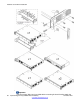

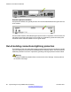

brackets to the control unit. As indicated in the diagram, the rack mounting bracket can
be used in several positions on the unit.
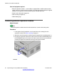
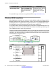
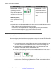
External expansion modules
External expansion modules should be connected to the control unit before power is applied
to the control unit. Ensure that modules are attached in the order that matches the planned or
pre-built configuration.
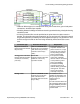
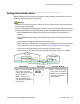
External expansion modules connect to the control unit using an expansion interconnect cable.
Each module is supplied with an expansion interconnect cable and a power supply unit. An
appropriate local specific power cord for the power supply unit must be ordered separately.
• Each external expansion module is supplied with a blue 1 meter (3'3'') expansion
interconnect cable. This cable must be used when connecting to expansion ports on the
rear of a control unit.
• When connecting to expansion ports on a 4-port expansion card, a yellow 2-meter (6'6")
expansion interconnect cable can be used in place of the standard blue cable. Four yellow
cables are supplied with the 4-port expansion card.
Installation requirements
• Installation space either on or under the control unit
• Switched power outlet socket
• Available EXPANSION port on the control unit
• Functional grounding requirements — connection of a functional ground is:
• recommend for all modules
• mandatory for analog trunk modules
• Protective grounding requirements — connection of a protective ground via surge
protection equipment is:
• mandatory for analog trunk modules in the Republic of South Africa
• mandatory for digital station and phone modules connected to out-of-building
extensions
• mandatory for digital station V2 and phone V2 modules
Tools required
• Manager PC
• Tools for rack mounting (optional)
External expansion modules
Implementing the Avaya B5800 Branch Gateway November 2011 63