
User's Manual


1. Enter the add signaling-group n command, where n is an available signaling group
number.
2. Enter the following values for the specified fields and retain the default values for
all remaining fields.
a. In the Group Type field, enter sip.
b. In the Transport Method field, enter tls.
c. In the IMS Enabled? field, enter y.
d. In the Near-end Node Name field, enter the IP node name added for the
Communication Manager Feature Server.
e. In the Far-end Node Name field, enter the IP node name added for the
Avaya Aura
®
Session Manager.
f. In the Near-end Listen Port field, enter 5061.
g. In the Far-end Listen Port field, enter 5061.
h. In the Far-end Network Region field, enter the IP network region
number assigned to the Avaya Aura
®
Session Manager.
i. In the Far-end Domain field, enter the SIP domain name.
j. In the DTMF over IP field, enter rtp-payload.
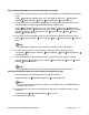
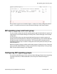
The screen below shows signaling group 42 which is used in the example configuration as the
primary signaling group.
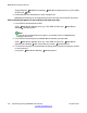
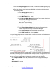
The screen below shows signaling group 32 which is used in the example configuration as the
“Secondary” signaling group to be associated with trunk group 32 for routing local PSTN calls
from branch phones to Avaya Aura
®
Session Manager. Note that all the settings for this
signaling group are identical to those for signaling group 42 except the following:
• The Transport Method is set to tcp (the port numbers will change automatically to
5060).
• IMS Enabled? is set to n.
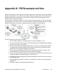
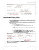
PSTN example call flow
318 Implementing the Avaya B5800 Branch Gateway November 2011
Comments? infodev@avaya.com