Avaya Solution & Interoperability Test Lab Application Notes for Configuring Multi-Tech FaxFinder® IP Fax Server with Avaya Aura® Communication Manager and Avaya Aura® Session Manager via SIP Trunk Interface - Issue 1.0 Abstract These Application Notes describe the procedures for configuring the Multi-Tech FaxFinder® IP Fax Server with Avaya Aura® Communication Manager and Avaya Aura ® Session Manager using a SIP trunk interface.
1. Introduction These Application Notes describe the procedures for configuring Multi-Tech FaxFinder® IP Fax Server with Avaya Aura® Communication Manager and Avaya Aura® Session Manager. FaxFinder is an appliance-based fax server solution that sends and receives faxes over an IP network. FaxFinder utilizes T.38 Fax over Internet Protocol (FoIP) for sending media. In the tested configuration, FaxFinder interoperated directly with Avaya Aura® Session Manager to send/receive faxes using SIP signaling. 2.
Platform Device TN2302, G450, MM760 TN2602 DSP Resources per Platform Device 64 64 DSP Resources per FoIP Call 4 1 Note that the SIP trunk group on Communication Manager for connecting to Session Manager at each site, as well as the SIP or ISDN-PRI trunk group for connecting the 2 sites must be configured with adequate number of trunk group members to support the number of simultaneous fax calls intended. 2.4.
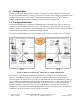
3. Configuration The test configuration was designed to emulate two separate sites with multiple Port Networks at one site, and modular Gateway resources at the other site. Each site was configured with Multi-Tech FaxFinder® IP Fax Server, Avaya Aura® Communication Manager and Avaya Aura ® Session Manager. Figure 1 illustrates the configuration used in the tested configuration. 3.1.
Site B had an Avaya S8300 Communication Manager Server in an Avaya G450 Media Gateway. The FaxFinder server at this site communicated with Session Manager via SIP. On the Avaya G450 Media Gateway, the signaling and media resources supporting a SIP trunk connected to Session Manager were integrated directly on the media gateway processor. Endpoints at this site included Avaya 9600 Series IP Telephones (with H.323 and SIP firmware), and an analog fax machine.
4. Equipment and Software Validated The following equipment and software/firmware were used for the sample configuration provided: Equipment Avaya S8800 Servers (at both sites) Avaya S8800 Server (at Site A) Avaya G650 Media Gateway (at Site A) - 2 CLANs - 2 MedPros – TN2302 - 2 MedPros – TN2602 Avaya S8300D Server (at Site B) Software/Firmware Avaya Aura® Session Manager 6.0 (6.0.2.0.602004) 6.1 (6.1.2.0.612004) Avaya Aura® System Manager 6.0, 6.1 Avaya Aura® Communication Manager 6.0 SP1 R016x.00.0.345.
5. Configure Avaya Aura® Communication Manager This section describes the Communication Manager configuration necessary to interoperate with Session Manager and Multi-Tech FaxFinder® IP Fax Server. Connectivity via SIP and PRI trunks between the two sites used existing configurations which follow standard practices.
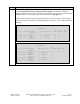
Step 1. Description Verify Communication Manager License Use the display system-parameters customer-options command to verify that the Communication Manager license has proper permissions for features illustrated in these Application Notes. Navigate to Page 2, and verify that there is sufficient remaining capacity for SIP trunks by comparing the Maximum Administered SIP Trunks field value with the corresponding value in the USED column.
Step 2. Description Identify IP Interfaces Use the list ip-interface clan and list ip-interface medpro commands to identify IP interfaces in each network region. Interfaces in cabinet 01 (port network 1) as indicated in the Slot field are in IP network region 1 as indicated in the Net Rgn field. Testing with the TN2302 and TN2602 circuit packs were done separately. When testing with the TN2302, the TN2602 was disabled (turned off) and vice versa as indicated in the ON field.
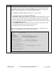
Step 3. Description Administer IP Network Region 1 The configuration of the IP network regions (Steps 3 – 6) was already in place and is included here for clarity. At Site A, the Avaya G650 Media Gateway comprising port network 1 and all IP endpoints were located in IP network region 1. Use the display ip-network-region command to view these settings. A descriptive name was entered for the Name field.
Step 4. Description Administer IP Network Region 1 – Continued On Page 4, codec sets are defined for inter-region calls. In the case of the compliance test at Site A, calls from IP network Source Region 1 to IP network region 2 (dst rgn 2) used codec set 1. The default values were used for all other fields. At Site B, only one IP network region was used, so no inter-region settings were required. display ip-network-region 1 Source Region: 1 5. 6.
Step 7. Description Administer IP Node Name Use the change node-names ip command to create a node name that maps to the Session Manager IP address. This node name is used in the configuration of the SIP trunk signaling group in Step 11. change node-names ip Page 1 of 2 IP NODE NAMES Name CLAN1A CLAN2A CM-Remote DemoSM Gateway001 MEDPRO1A MEDPRO1A-2 MEDPRO2A MEDPRO2A-2 TR18300 8. IP Address 10.64.22.16 10.64.22.19 10.64.21.111 10.64.20.31 10.64.22.1 10.64.22.15 10.64.22.17 10.64.22.18 10.64.22.20 10.
Step Description 10. Administer IP Codec set – Fax settings On Page 2, set the FAX Mode field to t.38-standard. This is necessary to support the FaxFinder server assigned to IP network region 2. The Modem Mode field should be set to off. Leave the FAX Redundancy setting at its default value of 0. A packet redundancy level can be assigned to improve packet delivery and robustness of FAX transport over the network (with increased bandwidth as trade-off). Avaya uses IETF RFC-2198 and ITU-T T.
Step Description 11. Administer SIP Signaling Group For the compliance test, a signaling group with the associated SIP trunk group was used for routing fax calls to/from the FaxFinder server via Session Manager. For the compliance test at Site A, signaling group 12 was configured using the parameters highlighted below. All other fields were set as described in [3]. The Group Type was set to sip.
Step Description 12. Administer SIP Trunk Group For the compliance test, trunk group 12 with the associated signaling group was used for routing fax calls to/from Session Manager. Trunk group 12 was configured using the parameters highlighted below. All other fields were set as described in [3]. On Page 1: The Group Type field was set to sip. A descriptive name was entered for the Group Name.
Step Description 13. Administer SIP Trunk Group – continued On Page 3: Set the Numbering Format field to public. This field specifies the format of the calling party number sent to the far-end. Default values may be used for all other fields.
Step Description 15. Administer Route Pattern Use the change route-pattern command to create a route pattern that will route fax calls to the SIP trunk that connects to the FaxFinder server. The example below shows the route pattern used for the compliance test at the Main Site. A descriptive name was entered for the Pattern Name field. The Grp No field was set to the trunk group created in Steps 12–13.
6. Configure Avaya Aura® Session Manager - Overview This section covers the configuration of Session Manager at Site A. Session Manager is configured via an Internet browser using the administration web interface. It is assumed that the setup screens of the administration web interface have been used for initial configurations. For additional information on these installation tasks, refer to [3].
6.1. Configure Session Manager - Details This section summarizes the applicable user-defined parameters used during the SIP installation procedures. Step 1. Description Login Access the System Manager administration web interface by entering https:///SMGR as the URL in an Internet browser, where is the IP address (or FQDN) of the System Manager server. Log in with the appropriate credentials. 2.
Step 3. Description Create a SIP Entity for the FaxFinder Server - Continued Enter a descriptive Name such as RB_FaxServer and enter the FQDN or IP Address for the FaxFinder server as shown below. Select Other for the Entity Type. All other settings were defaults. 4. Create an Entity Link for the FaxFinder Server An Entity Link establishes the details of how Entities will communicate with each other. Use the Add button to create a new link.
Step 5. Description Create a Routing Policy Navigate to Routing\Routing Policies and click New to create a routing policy for incoming calls to the FaxFinder server. The illustration below was captured after the Policy RB_Fax_Server_2 had been created and the following steps will describe how this policy was created. A Routing Policy consists of a definition of the SIP Entity as Destination, the Time of Day the policy applies, and the Dial Patterns that will trigger this particular policy.
Step 6. Description Create or Modify Dial Patterns Associating a dial pattern with a SIP Routing Policy instructs Session Manager how to route calls matching the administered Dial Pattern(s). In the test, existing Routing Policies were modified for routing to endpoints or Entities at the Remote Site, and new Dial Patterns were created to route to the Main Site and Remote Site Fax Servers using the existing and new routing policies. In the snapshot below, the Dial Patterns were previously created.
Step 7. Description Create or Modify Dial Patterns – Continued The entries required to create the new Dial Pattern for routing calls to the FaxFinder server at the Main Site are illustrated below. The Pattern, Min and Max number of digits, and SIP Domain entries were used for this Dial Pattern definition. Click Add to associate the dial pattern with an existing Routing Policy, in this case the RB_Fax_Server_2 policy created in Step 5 above.
7. Configure Multi-Tech FaxFinder® IP Fax Server This section describes the configuration of Multi-Tech FaxFinder® IP Fax Server. For further instructions on configuring FaxFinder, consult the Administrator User Guide [4]. 7.1. Configure FaxFinder Details The configuration procedures covered in this section include tasks in the following sub categories: 1.
Step 1. Description System Configuration: Launch FaxFinder web configuration tool The FaxFinder configuration is performed using a web browser. Access the tool by pointing your web browser to http://. The home page is displayed below: System Configuration: Configure Network Settings FaxFinder ships with a default network address, so initial configuration needs to be performed from a browser on a host manually configured with an address on the same network segment.
Step Description System Configuration: Configure SMTP Settings FaxFinder can be configured to generate email alerts for a number of events. Navigate to System Configuration > SMTP to configure the outgoing mail gateway, click Save to commit the changes. Below is an example: System Configuration: Configure Time Settings Set the current date and time, it is also recommended that an NTP server be configured to keep the system time in synch with other servers.
Step Description System Configuration: Configure Printers and Network Shares FaxFinder can be configured to deliver inbound faxes to an email address, to a printer, or to a network share. In the tested configuration, all inbound faxes were saved to a network share. To add a share, click the Add link and provide the path and credentials for the share.
Step 2. Description Fax Configuration: Configure SIP/T.38 Navigate to Fax Configuration > SIP / T.38 and provide the appropriate information for the Session Manager in the SIP section. Note that at this time, UDP is the only option for communications with Session Manager. Default T.38 settings were used in the compliance tests. RAB; Reviewed: SPOC 7/12/2011 Solution & Interoperability Test Lab Application Notes ©2011 Avaya Inc. All Rights Reserved.
Step Description Fax Configuration: Configure Inbound Routing Navigate to Fax Configuration > Inbound Routing to define Global, Default and specific Recipient routing rules. For each rule, a network share, email address or printer can be defined for fax delivery. Click on Edit in each section to define or modify the respective rules.
Step Description Fax Configuration: Configure Outbound Rules Configuration is needed only if an archive of outbound faxes is to be used. In the tested configuration, outbound archiving was configured to save in PDF format to the network share that was used in the previous step for inbound fax delivery. This was intermittently enabled and disabled by clicking on the Enable Outbound Archive selection on the Fax Configuration > Outbound page.
Step 3. Description Configure Users and Contacts Two users were configured, an administrator (admin) and a standard user (test). To create a user, navigate to the Users tab, then click the Add link and enter a Username, Full Name, Password and Email address for each user. In addition, if a user has a unique inbound fax extension, a routing rule can be created by providing information in the lower section of the form.
8. Verification Steps The following steps may be used to verify the configuration: From Avaya Aura® Communication Manager SAT, use the status signaling-group command to verify that the signaling groups are in-service. From Communication Manager SAT, use the status trunk-group command to verify that the trunk groups are in-service. Verify that fax calls can be placed to/from Multi-Tech FaxFinder® IP Fax Server servers at each site.
9. Conclusion These Application Notes describe the procedures required to configure Multi-Tech FaxFinder® IP Fax Server interoperate with Avaya Aura® Communication Manager and Avaya Aura® Session Manager. Multi-Tech FaxFinder® IP Fax Server successfully passed compliance testing. 10. Additional References [1] Avaya Aura™ Communication Manager Feature Description and Implementation, Doc # 555245-205, Release 6.0, Issue 8.0, June, 2010.
©2011 Avaya Inc. All Rights Reserved. Avaya and the Avaya Logo are trademarks of Avaya Inc. All trademarks identified by ® and ™ are registered trademarks or trademarks, respectively, of Avaya Inc. All other trademarks are the property of their respective owners. The information provided in these Application Notes is subject to change without notice.