
User's Manual


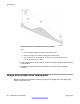
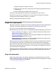
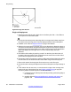
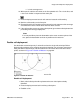


Figure 60: Single cell distance
Single cell deployment
1.
Identify the initial critical points. Mark them on thefloor plan with a . Use different
colour pencils for each critical point.
2. Choose the first critical point at the edge of the coverage area furthest away from
the centre of the coverage area. Place the deployment tool at this critical point.
3.
Establish a link. Refer to
Deployment tool on page 76
for details.
4. Measure the range into the coverage area in a few directions to determine where a
cell centre can be located, and still remain within range of the critical point. Observe
the deployment tool handset RSSI value while moving away from the basestation.
When the display value changes from 7 to 6, the cell boundary has been
detected.
5. Record the cell boundary by marking a small X on the floor plan where the cell
boundary value was reached. Use a pencil that is the same colour as the critical
point where the deployment tool is located.
6. Repeat step 4 and 5 several times, walking in different directions to determine where
the cell centre can be located and still remain within range of the critical point.
7. Draw a thin contour line through the Xs to mark an arc on the floor plan.
8. Choose the other critical point adjacent to the first critical point and repeat steps 3
to 7.
9. If the contour lines do not cross, or cross close to the edge of the coverage area
between the two critical points, then see
Double cell deployment on page 99
.
Choose a position on the floor plan for the cell centre that:
a. is furthest from the critical points and still provides good audio quality at
the critical point,
b. complies with the
Rules and guidelines for selecting cell centres on
page
60, and
Site planning
98 DMC DECT Fundamentals August 2012
Comments? infodev@avaya.com