
User's Manual


See Figure 35: Example of a cell centre boundary on page
69 for an example of a
cell boundary.
6. Mark and label the cell boundary on the floor plan
Follow these steps:
a. Mark each office within the cell that is isolated from the office area.
b. Label any subsequent critical point on the floor plan the following symbol:
c. Mark the cell contour on the floor plan. Trace a contour line through the
Xs with a marker
.
d. Trace the cell boundaries and cell centres with coloured markers.
7. Identify new critical points.
Follow these steps:
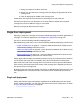
a. Identify one new critical point slightly inside of where the cell boundary
meets the outside wall. In
Figure 36: Example of new critical points (P8
and P9) on page
69, this new critical point is P9.
b. Identify another new critical point which is adjacent to the first new critical
point. Locate this critical point on the opposite side of the cell boundary
area. In
Figure 36: Example of new critical points (P8 and P9) on
page 69
, the cell boundary area is IC1 and the new critical point is P8.
8. Mark and label these new critical points on the floor plan with the symbol:
See step 6 on page 93 for details.
9.
Using the critical points from step
7 on page
93, demarcate new cell contours, a
new cell centre and a new cell boundary.
See step
2 on page 91 to step 5 on page
92 starting on step
2 on page
91 for
details.
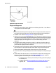
Note:
Cell contour arcs must pass near the cell boundary of adjacent cells. For an
example of this, see Figure 37: Example of deployment for cell centre 1C2 on
page
70.
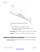
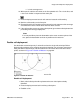
10. Demarcate additional cell contours, centres and boundaries at the other end of the
building.
Repeat step
1 on page 91
to step
8 on page
93 as necessary to demarcate new
cell boundaries at the other end of the building. In
Figure 38: Example of deployment
for cells 1C3 and 1C4 on page
70, new cells are formed around cell centres IC3
and IC4.
11. Identify new critical points:
Deploying DECT
DMC DECT Fundamentals August 2012 93