
User's Manual
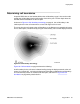
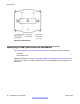


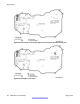

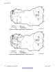

Figure 29: Example cell boundaries
Figure 30: Points, centres, and boundaries on the floor plan
Figure 30: Points, centres, and boundaries on the floor plan on page 65 shows a typical floor
plan marked-up after determining subsequent cell boundaries.
The completed floor plan would
appear as follows:
• Initial critical points are shown at P1, P2, P3, and P4.
• Cell centres are located where arcs from P1/P2, P3/P4 intersect.
• 2C1 and 2C2 show cell centres or basestation locations.
• Dashed and dotted lines show cell boundaries.
• Additional critical points are shown at P5 P6 P7 P8.
• 2C3 and 2C4 cell centres provide full coverage of the floor.
Deployment
DMC DECT Fundamentals August 2012 65