
User's Manual


• Handset handover continues without interruption.
• Handsets are distributed equally between the system DMC cards.
• All calculations are based on resident handset users. Visiting handset users have a
negligible effect on traffic. In unusual circumstances where a site has a large number of
visiting handset users, traffic capacity can require adjustments.
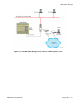
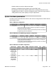
System hardware parameters
The tables in this section detail the minimum and maximum configurations for DECT
with the
Concentration feature.
Table 1: Minimum configuration
System type Cabinets DMC8 DMC8-E Basestation Handset
All systems 1 1 0 1 to 8
††
1 to 510
†
† Due to the maximum number of DCS sets per DMC card. Subject to
engineering rules and constraints.
†† Due to the maximum number of basestations per DMC card. Subject
to engineering rules and constraints.
Table 2: Maximum CS 1000M (Large System) configuration
System type Cabinets DMC8 DMC8-E Basestation Handset
CS 1000M 2 30 2 256
††
16 320
†
† Due to the maximum number of DCS sets per DMC card. Subject to
engineering rules and constraints.
†† Due to the maximum number of basestations per DMC card. Subject
to engineering rules and constraints.
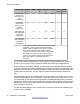
Table 3: Maximum CS 1000E configuration
System type Cabinet
s
DMC8 DMC8-
E
Basestatio
n
Handse
t
PRI
Cards
MC32
Cards
MG 1000E
Cabinet / MG
1010E Chassis
(one-shelf
configuration)
1 5 1 48
††
3060
†
1 3
MG 1000E
Cabinet / MG
1010E Chassis
(two-shelves
configuration)
2** 11 2 104
††
6630
†
1 6
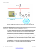
System concentration traffic
DMC DECT Fundamentals August 2012 39