
User's Manual
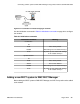


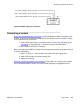
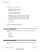

Figure 220: DMC8 debug port connections
Connecting a modem
Figure 220: DMC8 debug port connections on page
329 shows the DMC connected to a PC
as DCE. To connect to a modem, the DMC has to act as DTE (because the modem is DCE).
This is achieved in one of two ways:
1. Cross the TX and RX of the connections shown in
Figure 220: DMC8 debug port
connections on page
329 (that is, swap pins 2 and 3 of the DB-9 cable).
2. Use a modem eliminator (null modem).
Before connecting to the DMC, the modem must be configured as follows using Hyper Terminal
or similar (19200 baud):
1. ats0=1: s0 (zero) = 1, which enables auto answer after one ringing cycle.
2. at&d0: DTR override; the modem ignores DTR.
3. at&w0: Save settings.
Figure 221: 3COM US Robotics modem settings on page 330
is an example of the settings
from a 3COM US Robotics modem. The most important settings are highlighted in bold.
Monitor port physical connection
DMC DECT Fundamentals August 2012 329