
User's Manual
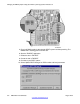


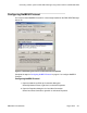


Figure 216: DMC8 relay card connection to a remote DMC DECT Manager server
DECT relay board to remote modem
Refer to Table 52: NTCW12AA cable to MDF connections on page
316 when connecting the
NTCW12AA cable to the MDF.
Table 52: NTCW12AA cable to MDF connections
DMC Relay card
MDF connection
Cable colour DB-25 connector
pin number
Signal designator
T1 Gray 8 V.24DCD
R2 Yellow 4 V.24RTS
T3 Blue 2 V.24TXD
R3 Red 3 V.24RXD
T4 Pink 7 V.24GND
Note:
The BIX tip and ring connections shown in Table 52: NTCW12AA cable to MDF
connections on page 316
correspond to standard BIX designation. The first pair is labeled
T0 and R0. See Communication Server 1000M and Meridian 1: Large System Installation
and Commissioning (NN43021-310) for more information.
Changing the DMC8 jumper setting after DECT system upgrade to Release 5.0
316 DMC DECT Fundamentals August 2012
Comments? infodev@avaya.com