
User's Manual


Connect the DB-25 connector end and the NTCW12AA cable end into the
A0773252 null modem adapter
.
4. Connect the DB-9 end into the chosen PC COM port.
Refer to
Table 39: NTCW12AA cable to MDF connections on page 201
when connecting the
NTCW12AA cable to the MDF.
Table 39: NTCW12AA cable to MDF connections
DMC Relay card
MDF connection
Cable colour DB-25 connector
pin number
Signal designator
T1 Gray 8 V.24DCD
R2 Yellow 4 V.24RTS
T3 Blue 2 V.24TXD
R3 Red 3 V.24RXD
T4 Pink 7 V.24GND
Note:
The BIX tip and ring connections shown in Table 39: NTCW12AA cable to MDF
connections on page 201
correspond to standard BIX designation. The first pair is labeled
T0 and R0.
Dial-up configuration
For the DMC DECT
Manager to communicate over PPP with the DECT system, a RAS service
must be configured for dial-out using the appropriate modem.
Note:
The DECT system can also communicate directly over a modem to a remote DMC DECT
Manager.
Note:
It is also possible to connect to DMC8 relay cards using PPP
(serial connect). When
connecting to a DMC8 relay board using PPP, Avaya recommends that jumpers J6, J7, J8,
and J9 be strapped for V.24 on the DMC.
Complete the following steps to configure the dial-up connection.
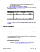
Configuring a dial-up connection
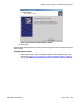
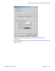
1. Open Control Panel > Phone and Modem Options. Click the Modems tab, if not
selected. See
Figure 132: Phone and Modem Options window on page 202.
Upgrade a DECT system to an SNMP-managed system
DMC DECT Fundamentals August 2012 201