
User's Manual
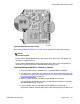

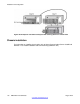


Plug the cable into the lower port of the DMC8 in slot 7. Plug the other end of the
cable into the arrow pointing left port of the DMC8-E in slot 8. See the following
examples:
Figure 95: Example of a full system housed in two IPE shelves on page 165
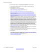
Figure 96: Example of a 16 card system housed in two IPE shelves on page 166
,
and
Figure 97: Example of a 17 card system housed in two IPE shelves on page 167
.
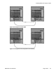
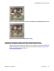
4. Connect the NTCW11EA DMC8-E to DMC8-E inter-IPE shelf or inter-cabinet cable,
if required.
Plug the DMC8-E to DMC8-E cable into each DMC8-E lower port. See the examples
given in the previous step as well as the following examples:
Figure 101: Example of an 8-card system in two Cabinets on page 173, and
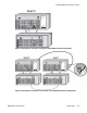
Figure 105: Example of two-shelf 15-card system in two MG1000E Chassis and
Expanders on page 175.
Installing the DMC DECT application
Refer to Using the DMC DECT
Manager Avaya Communication Server 1000 (NN43001-142)
for information about installing DMC DECT Manager.
Connecting to a DECT system
Refer to section PBX system configuration of the NTP
Using the DMC DECT Manager Avaya
Communication Server 1000 (NN43001-142).
for information about connecting DMC DECT Manage to a DECT system.
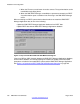
Synchronizing the DECT Application to a DECT system
When the DECT
Manager connects to DECT, synchronization occurs. Synchronization
compares the database on the DECT Manager to the DECT system. Database mismatches
are flagged by dialog boxes. The opportunity is then given to change either the system data
or manager data.
A number of synchronization steps occur during connection. The Synchronization process
flags changes made to a DECT system database by other managers.
Two types of synchronization occur when the connection state goes from Disconnected to
Connected:
Installing the DMC DECT application
DMC DECT Fundamentals August 2012 179