
User's Manual
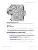
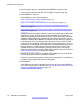
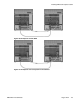

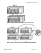
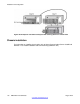
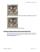

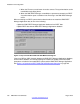

Figure 109: NTCW11EA DMC8-E to DMC8-E faceplate cable
Caution:
Service Interruption
The NTCW1
1EA DMC8-E to DMC8-E faceplate cable has four sets of movable ferrites. The
position of the ferrites on the cable is important.
Each end of the cable must have a group of 20 ferrites. One quarter of the distance from
each end of the cable must have a group of 10 ferrites. The maximum length of the cable is
1.5 meters, limiting the position of DECT shelves 0 and 1 to adjacent IPE modules or CS
1000E cabinets.
Consult the work order to determine the position of the terminator plugs, then perform the
following steps.
Installing faceplate cables and inter-shelf/cabinet cable
1. Connect the DMC8 to DMC8 faceplate cables.
Arrange the NTCW11AA DMC8 to DMC8 cables so that the DMC8 to DMC8-E cable
is connected into the ports shown in:
Figure 95: Example of a full system housed in two IPE shelves on page 165
and
Figure 98: Example of an eight card system housed in one IPE shelf on
page
167.
2. If required, connect the NTCW11FA DMC8 to DMC8 1m faceplate cable between
MG1000E Chassis and Expander.
For examples see
Figure 104: Example of one-shelf 7-card system in MG1000E
Chassis and Expander on page 175
and
Figure 105: Example of two-shelf 15-card system in two MG1000E Chassis and
Expanders on page
175.
3. If required, connect the NTCW11BA DMC8 to DMC8-E cable on the IPE shelf. Not
required on Option 11C Cabinet.
Installation and configuration
178 DMC DECT Fundamentals August 2012
Comments? infodev@avaya.com