
User's Manual
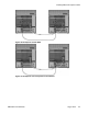

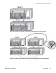
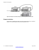
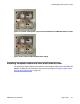

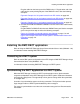

Figure 107: Chassis and Expander connected with 2 NTDK95 and CE-MUX/DS-30SX bus cables
Figure 108: MG 1000S and MG 1000S Expander cabling
Installing faceplate cables and inter-shelf/cabinet cable
Consult the work order to determine the position of the faceplate cable layout and NTCW1
1EA
DMC8-E to DMC8-E inter-shelf cables, then perform the steps in
Installing faceplate cables
and inter-shelf/cabinet cable on page 178
.
Installing DMC8 and faceplate cables
DMC DECT Fundamentals August 2012 177