
User's Manual
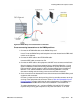

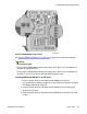
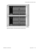
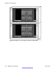
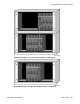


Figure 93: DMC8 Relay card to basestation connections
Cross-connecting basestations to the DMC8 positions
1.
Connect the NTCW12DA cable to the DMC8 Relay card.
Insert P1 into the DMC8 Relay card backplane connector located on the PBX shelf/
module or the Cabinet.
2. Connect the MDF cable to the NTCW12DA cable.
Insert the MDF cable connector into P2.
3. Connect the MDF cable to the equipment side MDF cross-connect terminal block.
See the chapter in Avaya Communication Server 1000M and Meridian 1: Large
System Installation and Commissioning (NN43021-310) that discusses cabling
lines and trunks. See the chapter in Avaya Communication Server 1000M and
Meridian 1: CS 1000E Installation and Commissioning (NN43011-310) that
discusses installing and connecting cross-connect terminal to cabinets.
4. Cross-connect from the basestation house-side connector to the DMC8 Relay card
equipment side connector.
Connect a jumper wire from the tip and ring of the house-side connector to the tip
and ring of the equipment-side connector. Refer to
Table 38: Basestation tip and
ring connections on page 159 for the tip and ring designators. For DMC8s, type
NTCW00AB and NTCW01AB connect from basestation 1 to basestation 8.
To support basestations 5, 6, 7, and 8 on NT8D37 (AA and DC) IPE modules
requires 24 tip and ring pair backplane to I/O panel connections. To re-cable
Installing DMC8 and faceplate cables
DMC DECT Fundamentals August 2012 161