
User's Manual


The jumper wire on the MDF must be at least UTP Cat 3. Avaya recommends UTP Cat 5,
as it provides a greater line length before signal degradation occurs.
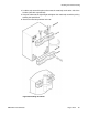
Cross-connecting basestations to the DMC8 positions
1. Cross-connect from the basestation house side connector to the DMC8 equipment
side connector.
Connect a jumper wire from the tip and ring of the house side connector to the tip
and ring of the equipment side connector. Refer to Table 38: Basestation tip and
ring connections on page 159 for the tip and ring designators. For DMC8s type
NTCW00AB and NTCW01AB, connect from basestation 1 to basestation 8.
Note:
To support basestations 5, 6, 7, and 8 on NT8D37 (AA and DC) IPE modules,
use 24 tip and ring pair backplane to I/O panel connections. To re-cable NT8D37
from 16 pair to 24 pair, see Avaya Communication Server 1000M and Meridian
1: Large System Installation and Commissioning (NN43021-310).
2. Cross-connect the remaining basestations.
Repeat step one until all basestations are cross-connected.
Note:
The BIX tip and ring connections shown in Table 38: Basestation tip and ring connections on
page 159
correspond to standard BIX designation. The first pair are labeled T0 and R0.
See Avaya Communication Server 1000M and Meridian 1: Large System Installation and
Commissioning (NN43021-310), chapter Planning and designating the Modular Distribution
Frame (MDF).
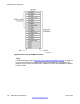
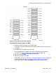
Table 38: Basestation tip and ring connections
Basestation number Basestation MDF connection DMC8 MDF connection
Basestation 1
T8 T8
R8
R8
T9
T9
R9
R9
Basestation 2
T10 T10
R10 R10
T11 T11
R11 R11
Basestation 3
T12 T12
R12 R12
T13 T13
Installing DMC8 and faceplate cables
DMC DECT Fundamentals August 2012 159