
User's Manual
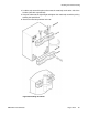
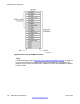
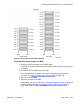


Figure 91: IPE I/O cable to Krone MD termination
Installing IPE module wiring to the MDF
1.
Identify the UTP Cat 5 twenty-five pair MDF cable.
Label both ends of the cable with the IPE module number and the I/O panel letter
designation.
2. Connect the IPE or cabinet end of the cable.
Insert the Amphenol
®
connector on the cable into the appropriate I/O panel
connector. See
Table 37: Colour code for 25 pair cable on page 156
.
3. Run the cable to the MDF.
4. Terminate the cable on the MDF.
For BIX MDF, refer to
Figure 90: IPE I/O cable to BIX MDF termination on page 154
to locate the BIX connectors and Table 37: Colour code for 25 pair cable on
page 156 to locate the cable colour code.
Installing additional IPE shelves or CS 1000E cabinets
DMC DECT Fundamentals August 2012 155