
User's Manual
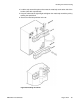
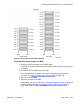


Unlock the sensor connector latches on the 36 pin orange/brown coloured
connector
, located to the left of the LED connector. Unplug the sensor connector.
8. Remove the EMI perf panel.
Lift directly up.
9. Place the new module on top of the column.
Keep hands and fingers out from under the module when placing the module on top
of the equipment column.
10. Connect the new module wiring.
Install the sensor connector of the new module into the vertical connector housing
of the module below.
11. Secure the new module.
Insert the five bolts and lock washers into the base of the new module. Tighten the
bolts into the original module.
12. Attach the power cable.
Connect the ribbon cable of the new module to J2 of the module below.
13. Reinstall the EMI perf panel and the LED.
Install the LED connector and the sensor connector on the new module.
14. Replace the air grills and covers.
Reverse the procedure for steps 1 to 4.
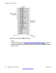
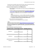
Installing IPE module wiring to the MDF
Consult the work order to determine the layout of the module I/O panel to MDF cabling route,
then perform the steps in Installing IPE module wiring to the MDF on page 155
.
Caution:
Service Interruption
The existing MDF cabling can be used; however
, Avaya recommends UTP Cat 5 – NTCW15,
NTCW16, or NTCW17 MDF to PBX cabling, as it provides a greater line length before signal
degradation occurs.
Installing additional IPE shelves or CS 1000E cabinets
DMC DECT Fundamentals August 2012 153