
User's Manual


Note:
If there are other twisted pairs available then ensure that the other pairs in the
cable are not used for analogue interfaces.
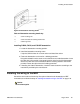
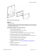
4. Connect the free end of the NTCW10 cable into the RJ45 Connection Box.
Note:
The BIX tip and ring connections shown in Table 35: Basestation RJ45 to BIX MDF
connections on page 133 correspond to standard BIX designation.
The first pair are labeled
T0 and R0. See Communication Server 1000M and Meridian 1: Large System Installation
and Commissioning (NN43021-310), chapter Planning and designating the Modular
Distribution Frame (MDF).
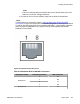
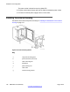
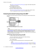
Figure 72: RJ45 Connection Box pin-out
T
able 35: Basestation RJ45 to BIX MDF connections
Basestation number RJ45 Connection Box MDF connection
Basestation 1
5 T8
4
R8
6
T9
3
R9
Basestation 2 5 T10
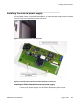
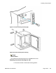
Installing the basestation
DMC DECT Fundamentals August 2012 133