
User's Manual
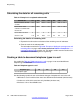
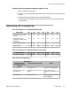
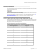
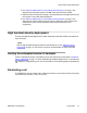
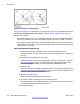


Figure 67: Example of a subdivided cell
In Figure 67: Example of a subdivided cell on page 1
18, cell 1C1 has 140 handset users and
cell 1C2 has 100 handset users. For example,
Table 25: Cell re-engineering on page 1
13
indicates the following:
• If the handset users in cell 1C1 are all handset only users, one cell can support 39 handset
only users. Therefore, four cells are needed to support 140 users (140÷39 = 3.5 cells).
• If the handset users in cell 1C1 are handset and wired telephone users, and one cell can
support 83 users, then two cells are needed to support 140 handset and wired telephone
users (140÷83 = 1.6 cells)
High handset density deployment
1. Determine the number of handset users in the high handset density cell.
Count the number of users. Include users served by through-the-floor coverage of
this cell.
2. Calculate the cell subdivisions as required.
Divide the number of users by the appropriate value (12 or 20) shown in
Table 25:
Cell re-engineering on page 113. Round up the result to the next whole number.
The result equals the number of cells required after subdividing the cell.
3. Divide the cell.
Draw lines from the cell centre to the critical points on the cell boundary. Shown in
Figure 67: Example of a subdivided cell on page 1
18, the cell 1C1 divides into four
sectors and cell 1C2 divides into three sectors.
4. Relocate new cell centres.
Mark new cell centres within the sectored areas.
5. Check the number of handset users in the new cell areas.
Count the number of user offices within each smaller sector. Ensure there are fewer
user offices within the cell than the traffic limit.
6. Check the locations.
Site planning
118 DMC DECT Fundamentals August 2012
Comments? infodev@avaya.com