
User's Manual
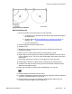
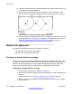
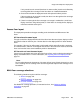
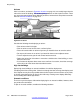
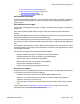
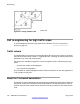
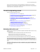
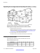
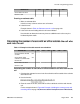
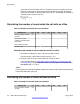

Figure 62: Multi-cell distance
Multi-cell deployment
1.
Choose a position on the floor plan for the cell centre that:
a. is furthest from the critical points and still provides good audio quality at
the critical point,
b. complies with the
Rules and guidelines for selecting cell centres on
page
60, and
c. is in the coverage area.
2. Place the deployment tool at critical point P1.
3. Establish a link.
4. Walk briskly into the coverage area away from the critical point until the cell
boundary is reached.
5. Mark a small X on the floor plan where the cell boundary is found.
6. Repeat step 4 and 5 several times, walking in different directions from the critical
point to establish an arc. The arc is at the cell boundary and is within range of the
critical point.
7. Draw a thin contour line to mark an arc through the Xs on the floor plan.
8. Repeat steps 4 through 7 walking into the coverage area of critical point P2.
9. Locate the cell centre on the arc along a line from the critical point that is equal
distant from the adjacent walls.
10. Mark each cell centre on the floor plan and label them 1C1 and 1C2.
11. Place the deployment tool at each cell centre.
12. Locate the cell boundary and mark it on the floor plan. (Mark the contours in dif
ferent
colours for easy differentiation of cell centres.)
13. Define and mark on the plan any subsequent critical points, where each cell
boundary crosses the edge of the coverage area.
Single and multiple floor deployment
DMC DECT Fundamentals August 2012 101