DMC DECT Fundamentals Avaya Communications Server 1000 Release 7.5 NN43120-114, 02.
© 2012 Avaya Inc. Copyright All Rights Reserved. Except where expressly stated otherwise, no use should be made of materials on this site, the Documentation, Software, or Hardware provided by Avaya.
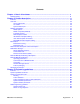
Contents Chapter 1: New in this release........................................................................................... 11 Revision History........................................................................................................................................ 11 Chapter 2: Product description......................................................................................... 13 Contents...........................................................................................
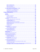
DECT on Cabinet system................................................................................................................. 44 DECT on Chassis system................................................................................................................ 44 DECT on CS 1000E......................................................................................................................... 44 Rules with new basestations...................................................................
Calculating the number of users without an office............................................................................ 110 Totalling the estimate for users in a cell........................................................................................... 111 Calculating the data for all remaining cells....................................................................................... 112 Creating a table to document telephone types in a cell......................................................
Compatibility..................................................................................................................................... 158 Cross-connecting basestations to the DMC8 positions.................................................................... 158 Cross-connecting basestations to the DMC8 Relay card................................................................. 160 Installing DMC8 and DMC8-E in an IPE shelf.........................................................................
DECT Systems window............................................................................................................................. 230 Opening Subscriptions, Boards, and RFP windows......................................................................... 230 Connecting to a DECT system......................................................................................................... 231 Establishing a permanent connection to a DECT system..................................................
Restoring subscription data to the serviceable DMC8 card............................................................. 279 Adding a DMC8 card to a DECT system................................................................................................... 279 Reusing a DMC8 card in another DECT system.............................................................................. 281 Removing and reinstalling a basestation for maintenance.......................................................................
Connecting a modem....................................................................................................................... 329 Terminal configuration............................................................................................................................... 330 Successful connection.............................................................................................................................. 330 Information collection..........................................
DMC DECT Fundamentals August 2012
Chapter 1: New in this release The following sections detail what is new in DMC DECT Fundamentals, NN43120–114 for Release 7.5: Feature changes • All DECT Messenger material has been removed. See DECT Messenger Fundamentals (NN43120-120). • DSP provisioning information has been added to System hardware parameters on page 39 and Installing DMC8 and DMC8-E in an Avaya Communication Server 1000E on page 170 and now aligns with the provisioning rules implemented in the ordering tools.
New in this release 12 DMC DECT Fundamentals August 2012 Comments? infodev@avaya.
Chapter 2: Product description Contents This section contains information on the following topics: Overview on page 13 Mobility card (DMC8) on page 17 Basestations on page 25 DECT handsets DMC DECT Manager on page 29 Multi-site Mobility Networking on page 33 Messaging and Alarms on page 35 Overview Avaya Integrated DECT (DECT) allows users to move freely about their work sites while conducting telephone conversations using wireless handsets.
Product description Figure 1: Main parts of the DECT system The DECT system is in a CS 1000M IPE shelf or a CS 1000E cabinet or chassis.
Overview backplane clock between two MG1000 chassis, MG 1010 chassis, or Option 11C cabinets, are shown in the figures below. For CS 1000E DECT installations that span more than 1 cabinet, the NTDW63AAE5 (Option 11C Cabinet Ethernet & Clock Reference Breakout Adapter) is used with the NTDW67AAE5 (Clock Reference Cable) to synchronize the backplane clock between two Option 11C cabinets.
Product description Figure 2: MGC Breakout Adapter for Option 11C Figure 3: MGC DECT Clock Reference Cable 16 DMC DECT Fundamentals August 2012 Comments? infodev@avaya.
Mobility card (DMC8) Synchronization port Figure 4: DECT synchronization Where multiple DECT systems share the same radio coverage area, the DECT synchronization port must be used. The DECT synchronization port is accessed through a Main Distribution Frame (MDF) connection. Failure to connect the DECT synchronization ports of each system can lead to service interruptions.
Product description All DMC8s support a Point-to-Point Protocol (PPP) connection to the DECT Manager with an NTCW12DA cable. The DMC8 card requires a NTCW25AA DECT Manager Ethernet (DME) daughterboard installed to support an Ethernet connection. Each DMC8 is programmed in the database using LD 10. The DMC8s are interconnected by faceplate cables, allowing them to pass information to each other. DMC8s must be in an IPE shelf or in a cabinet or chassis. There is no call switching in the DMC8 card.
Mobility card (DMC8) DMC8 - Expander (DMC8-E) The NTCW01AB DMC8-E DECT Mobility Card – Expander provides the same functions as a DMC card. The DMC8-E has additional circuitry required to regenerate faceplate cable signals when a system contains more than eight DMC8s. The DMC8-E connects two shelves or cabinets in a DECT system. Figure 7: DECT Mobility Card - Expander If the DMC8-E is used in an IPE module, it must be located in card slot 8. Do not install a DMC8 in slot 8 of an IPE module.
Product description c Green LED (indicates DECT sub-system status) d DMC8 to DMC8 faceplate cable port e DMC8 bypass faceplate cable port f DMC8-E to DMC8-E faceplate cable port g For future use Figure 8: DMC8 and DMC8-E faceplate features 20 DMC DECT Fundamentals August 2012 Comments? infodev@avaya.
Mobility card (DMC8) DMC Faceplate cables The faceplate cables form the 20 Mb/s bus that connects all DMCs in a DECT system. The faceplate cables meet the standard for Unshielded Twisted-Pair category of performance 5 (UTP CAT 5). Signaling and PCM are sent to all DMCs over the faceplate cables, allowing a DMC8 to pass a call to another DMC8. The following faceplate cables are used in DECT systems: 1. DMC to DMC faceplate cable (NTCW11AA) The cable extends the 20Mb/s bus to all DMCs. 2.
Product description Figure 9: DMC-E to DMC-E intershelf faceplate cable Caution: Service Interruption The DMC-E to DMC-E faceplate cable has four sets of movable ferrites. The position of the ferrites on the cable is important. Each end of the cable must have a group of 20 ferrites. One quarter the distance from each end of the cable must have a group of 10 ferrites. The maximum length of the cable is 1.
Mobility card (DMC8) Customers must use UTP Cat 5 faceplate cables supplied by Avaya. Faceplate termination must be used on the DMCs at both ends of the faceplate cabling. Faceplate cabling between DMC(-E) cards is slightly different for different Avaya CS 1000 system types. The following are the examples: IPE Shelves Faceplate Cabling The following figure describes the faceplate cabling within one IPE shelf.
Product description Figure 12: IPE inter-shelf faceplate cabling The above figure shows: 24 a IPE DECT shelf 0 b IPE DECT shelf 1 c DMC-E to DMC-E faceplate cable connection between DMC-Es on DECT IPE shelves (NTCW11EA) DMC DECT Fundamentals August 2012 Comments? infodev@avaya.
Basestations MG1000E Chassis faceplate cabling The following figure describes the MG1000E Chassis faceplate cabling.
Product description Basestations are IP40-compliant wall-mounted transceivers that provide digital radio links to handsets. Caution: Service Interruption For maximum line length before signal degradation occurs, use UTP Cat 5 cabling between the basestation and the shelf or cabinet. If the line length exceeds 100 ohms for the 4610 basestation, an external power supply must be used. The maximum distance when using external power with UTP Cat 5 cabling is approximately 1.7 km.
Basestations Basestation housing The basestation environmental housing is IP66 compliant. The housing must be used indoors if a basestation is subject to conductive pollution, or outdoors if basestations are mounted externally. Figure 15: Basestation environmental housing The environmental housing kit includes all of the relevant cables and installation material. The environmental housing mounts to existing walls. Signaling lines provide power to the external basestations.
Product description Figure 16: Basestation cell The cell radius varies from 20m to 100m.
DMC DECT Manager Note: Refer to each DECT Handset User Guide for a detailed description of how to use handset features and system features. DMC DECT Manager The DMC DECT Manager provides a point of access and control to manage DECT system on an Avaya CS system. DMC DECT Manager 2.0 runs on Windows 2000 Server, Windows 2000 Professional, Windows XP Professional, Windows Server 2003, and Windows 7.
Product description Common Services The following DECT management features are provided by DMC DECT Manager Applications: • DMC DECT Manager Alarm Management provides alarm collection and alarm processing, as well as the following: - a Windows-based alarm browser to view alarms that occur while the browser is open - an Alarm Notification application to notify personnel of an alarm occurrence by pager or e-mail.
DMC DECT Manager Figure 17: Local DMC DECT Manager server access to a DECT system by V.
Product description Figure 18: Local DMC DECT Manager server access to a DECT system by dedicated LAN Multi-site Mobility Networking subscriptions In Multi-site Mobility Networking (MSMN), users can take their DECT handsets to other sites in the network, and make and receive calls as if they were at their home location. A handset is subscribed in a given DECT system and can be used in one or many DECT systems.
Multi-site Mobility Networking The DECT Manager user programs the SARI in the DECT system. The DECT Manager provides the PARK during the on-air subscription, and the PARK is programed into the handset at subscription time. For example, a handset can be subscribed to a DECT system on the premises of a distributor, where the handset is not to be in operation. Then the subscription data is downloaded to a DECT system where the handset is to be in operation.
Product description Operating parameters All DMCs, either new, empty for redundancy, or used for basestation coverage, must have at least one handset configured to ensure system operation. Call forward from a MADN handset A MADN handset at a remote node can activate Call Forward (CFW) at the home node. When the handset shares a DN with another sets, the CFW lamp lights on the shared DN sets. If the handset is not the MARP, the shared DN MARP set can cancel call forward.
Messaging and Alarms Messaging and Alarms DECT Messenger provides text messaging from many different sources to various output devices, including DECT handsets. Messages can be sent from the following sources: • external alarm systems, for example nurse call, building alarms, process control • a mechanical system • the web or email • a DECT handset • contact panels, door switches etc.
Product description 36 DMC DECT Fundamentals August 2012 Comments? infodev@avaya.
Chapter 3: Engineering guidelines Contents This section contains information on the following topics: System capabilities and limits on page 37 DMC8 engineering guidelines on page 41 System capabilities and limits This section examines several issues surrounding DECT capabilities and limits. Information about system hardware and software parameters is also provided. System concentration traffic A DECT system without concentration supports a maximum number of 1024 handsets.
Engineering guidelines • At the IPE backplane interface – when all 32 speech channels to the DS30X interface on the a DMC8 are occupied, calls to and from handsets that have that specific DMC8 as their home DMC8 are rejected. • At the Network interface – usually the IPE shelf connectivity is a blocking configuration, where the number of network timeslots provided for a shelf is less than the actual number of terminals configured on that shelf.
System concentration traffic • Handset handover continues without interruption. • Handsets are distributed equally between the system DMC cards. • All calculations are based on resident handset users. Visiting handset users have a negligible effect on traffic. In unusual circumstances where a site has a large number of visiting handset users, traffic capacity can require adjustments.
Engineering guidelines System type Cabinet s DMC8 DMC8- Basestatio Handse E n t PRI Cards MC32 Cards MG 1000E Chassis with Expander (oneshelf configuration) 2 4 1 40†† 2550† 1 2 MG 1000E Chassis with Expander (twoshelves configuration) 4** 9 2 88†† 5610† 1 4 MG 1000E IPE shelf –MG XPEC (one-shelf configuration) 1 13 1 112†† 7140† 0 2 MG 1000E IPE shelf –MG XPEC (two-shelves configuration) 2** 26 2 224†† 14280† 0 4 ** Clock synchronization with the main cabinet or MG is
DMC8 engineering guidelines The DECT system components have the following capacities: • One NTCW00AB DMC8 or one NTCW01AB DMC8-E can support up to 8 basestations. • One C4600 basestation can support 6 active calls. • One C4610 basestation can support 12 active calls. • One C4610E basestation can support 12 active calls. Multiple DECT systems can co-exist in the same PBX system if they are synchronized to the same clock source. However, from a user perspective, the DECT systems are separate.
Engineering guidelines Table 4: DMC8 engineering guidelines for 6-channel RFP (basestation) and 12-channel RFP (basestation) System Large System Cabinet Chassis CS 1000E Number of basestations that can be phantom powered per shelf or cabinet Total eight 6-channel or six 6-channel + two 12-channel @ 0.5 km 128 seven 6-channel or five 6-channel + two 12-channel @1.0 km 112 seven 6-channel @ 1.7 km 112 new basestations – any mix at 1.
DMC8 engineering guidelines System Cabinet Chassis CS 1000E Basestation average line length Required number of unoccupied slots 1.7km for every 1 – 6 slots, one slot must be unoccupied 0.5 km for every 1 – 9 slots, one slot must be unoccupied 1.0 km for every 1 – 8 slots, one slot must be unoccupied 1.7km for every 1 – 15 slots, one slot must be unoccupied 0.5 km no restrictions 1.0 km no restrictions 1.7km no restrictions 0.5 km no restrictions 1.0 km no restrictions 1.
Engineering guidelines DECT on Cabinet system The Order Tool allows the first 40 basestations to be phantom powered. When more than 40 basestations are requested, the extra basestations are assumed to be local powered. Power adapters are provided as follows: • C4610 AC adapters = (sum of 6-channel and 12-channel basestations) – 80 • Adapters must be purchased separately DECT on Chassis system All basestations can be powered from the cabinet power supply.
Basestation combinations for handsets on a DMC8 0 0 58 117 176 176 220 220 220 1 19 77 136 195 220 220 220 220 2 38 97 155 214 220 220 220 3 57 116 174 220 220 220 4 76 135 194 220 220 5 95 154 213 220 6 114 173 220 7 133 192 8 152 220 Medium traffic for a 0.15 Erlang capacity Table 7: Number of handsets for a 0.
Engineering guidelines High traffic for a 0.2 Erlang capacity Table 8: Number of handsets for a 0.2 Erlang capacity on page 46 shows the 6-channel and 12-channel basestation combinations required to support a maximum number of handsets on a DMC card. The calculations are based on each handset generating 0.2 Erlangs of traffic. Table 8: Number of handsets for a 0.
Basestation combinations for handsets on a DMC8 Simplified guidelines Use Table 9: Handset capacity/DMC8 for Superloop/IPE on page 46 to calculate the superloop capacity.
Engineering guidelines 48 DMC DECT Fundamentals August 2012 Comments? infodev@avaya.
Chapter 4: Site planning Contents This section contains information on the following topics: Overview on page 49 Site survey on page 50 Deployment on page 58 Deployment tool on page 76 How to use the deployment tool on page 86 DECT Deployment Kit 2 on page 87 Deploying DECT on page 91 Correcting problems with audio quality on page 94 Deploying an external basestation on page 95 Single and multiple floor deployment on page 96 Cell re-engineering for high traffic areas on page 106 Cell division requirements
Site planning module includes information about a key piece of deployment equipment, the DECT Radio Deployment Tool. The section titled Preparing the tool for deployment on page 78 explains how to prepare equipment for deployment. Other modules describe in detail the procedures related to deployment. These procedures vary according to site details and user requirements. Site survey The site survey begins by researching the customer requirements.
Site survey Building details System deployment and installation depends upon the following building details. • Building identification • Construction materials, such as walls, floors, ceilings • Type of use, such as an office, hotel, factory, or store • Dimensions • Number of floors • Height of floors • Partitioning of floors Position and use of available cabling Cables that connect the basestation to the DECT system must meet or exceed the UTP Cat 3 standard.
Site planning Know in advance where coverage is required. Some examples of coverage areas are: • elevators • stairwells • toilets • outdoor areas Number of handset users The following information must be available. 1. The number of handset users 2. The potential growth of handset users 3. The areas of above average and below average traffic density Number of cells required to support traffic Traffic requirements are determined for each cell.
Site survey 4. Building information 5. Existing cable information 6. Basestation radio coverage information 7. Handset user information 8. Reviewing the work Methods and examples for surveying more detailed sites are shown in the Detailed Site Planning section of this guide.
Site planning 3. Obtaining site plans on page 55 4. Gathering building information on page 55 5. Identifying existing cabling on page 56 6. Profiling handset use on page 57 Gather survey items Obtain the following items before beginning the site survey. The items are not customer supplied. • Pick up the DECT tool kit (consisting of tripod and deployment tool kit). • Get the appropriate DECT Provisioning Record. • Gather a pencil, an eraser, a ruler, and coloured pencils.
Site survey Obtaining site plans Obtain two scaled plans. The scale is required to check wiring distances from the controller to the basestations. The scale is in the form of a measured line so that it remains in proportion to the floor plan through reduction copiers. Figure 21: Example of a site coverage floor plan Obtaining site plans Obtain two site plans/maps, with dimensions marked. One working copy to identify critical points, cell centres, and cell boundaries.
Site planning Record this information. If the building contains atriums, multiple floors, floors not all the same shape or any unusual conditions, see Multiple floor deployment on page 102. 5. Find the height of floors. Record this information. 6. Ask about the partitioning of floors. Record this information. 7. Discuss the details of furniture, cupboards, and machinery in the interior of buildings on every floor. Record this information. 8. Ask about other building details, as necessary.
Site survey 3. Ask about external or outdoor radio coverage. Record this information. 4. Discuss areas where radio coverage is not feasible or requires specific basestations. Record this information. 5. Discuss areas excluded from radio coverage due to the proximity of sensitive electronic equipment. Record this information. 6. Ask about objects inside buildings that can affect radio coverage. Record this information. 7.
Site planning Record this information. 6. Ask about the mobility of the users. For example, do the users move from cell to cell, or is the area of movement restricted, such that the users remain within one cell? Record this information. Deployment A deployment determines the locations of basestations and cells. The deployment process consists of the following steps. • Identifying initial critical points on the floor plan on page 58. • Locating cell centres on page 59.
Deployment Figure 22: Critical points Locating cell centres Figure 23: Cell centres on page 60 shows the following: • stairwell • second floor plan A cell centre is located by placing the deployment tool at one critical point, for example P1, then using the deployment handset to obtain a change in audio quality. The audio quality change determines the cell boundary contour. This process is repeated at an adjacent critical point, for example P2.
Site planning Figure 23: Cell centres Rules and guidelines for selecting cell centres Comply with the following when selecting cell centres. • Ensure that the installation complies with local electrical codes. • Install basestations indoors where there is no condensation and the temperature remains between 0°C and 50°C. • Install basestations within 1500 metres of the MDF. Wiring from the basestation to the shelf or cabinet must be at least UTP Cat 3.
Deployment Determining cell boundaries A specific RSSI value on the handset defines the cell boundary range. Links can be made outside the cell boundary but the audio quality of the link is poor. The link drops when the handset and the basestation are too far apart. As shown in Figure 24: Cell boundary terminology on page 61, the cell boundary is the furthest point from the cell centre where a clear radio signal can be heard.
Site planning Figure 25: Cell boundaries Identifying critical points and cell boundaries Figure 26: Additional critical points and cell boundaries on page 63 shows the following: • stairwell • second floor plan Additional critical points, shown in Figure 26: Additional critical points and cell boundaries on page 63 as P5, P6, P7, and P8, are identified to ensure basestation radio coverage for the entire area. 62 DMC DECT Fundamentals August 2012 Comments? infodev@avaya.
Deployment Figure 26: Additional critical points and cell boundaries Marking the points, centres, and boundaries on the floor plan This section describes how to label critical points, cell centres, and cell boundaries on the floor plan. Mark the information clearly on the floor plans during the survey. The customer, the sales group, the installer, and maintenance personnel must read these floor plans. Use a different colour for each cell.
Site planning For example, label a cell centre on the second floor as 2C3. The 2 before the C indicates that the cell centre is on the second floor. The 3 after the C indicates that this cell is the third cell in sequence in the site planning process. Table 10: Example cell labels Floor 64 Cell label First floor 2C1, 2C2, 2C3 Ground floor 1C1, 1C2, 1C3 Basement level one –1C1, –1C2, –1C3 Basement level two –2C1, –2C2, –2C3 DMC DECT Fundamentals August 2012 Comments? infodev@avaya.
Deployment Figure 29: Example cell boundaries Figure 30: Points, centres, and boundaries on the floor plan Figure 30: Points, centres, and boundaries on the floor plan on page 65 shows a typical floor plan marked-up after determining subsequent cell boundaries. The completed floor plan would appear as follows: • Initial critical points are shown at P1, P2, P3, and P4. • Cell centres are located where arcs from P1/P2, P3/P4 intersect. • 2C1 and 2C2 show cell centres or basestation locations.
Site planning Two copies of the floor plan are required. One copy is used during the site planning. The second copy is marked with the information from the site planning copy and attached to Provisioning records on page 125 for the installer. Deployment illustrations The illustrations in this section represent the deployment process from start to finish. 66 DMC DECT Fundamentals August 2012 Comments? infodev@avaya.
Deployment Figure 31: Example of initial critical points Figure 32: Cell contour of the initial critical point DMC DECT Fundamentals August 2012 67
Site planning Figure 33: Cell contour of the closest adjacent critical point to the initial critical point Figure 34: Example of a cell centre 68 DMC DECT Fundamentals August 2012 Comments? infodev@avaya.
Deployment Figure 35: Example of a cell centre boundary Figure 36: Example of new critical points (P8 and P9) DMC DECT Fundamentals August 2012 69
Site planning Figure 37: Example of deployment for cell centre 1C2 Figure 38: Example of deployment for cells 1C3 and 1C4 70 DMC DECT Fundamentals August 2012 Comments? infodev@avaya.
Deployment Figure 39: Identify new critical points (P11, P12, P13, P14, P15, P16, P17) Figure 40: Contours formed by critical points P11, P13 and P16 DMC DECT Fundamentals August 2012 71
Site planning Figure 41: Cell centre 1C5 formed by critical points P11, P13 and P16 Figure 42: Cell boundary 1C5 formed by critical points P11, P13 and P16 72 DMC DECT Fundamentals August 2012 Comments? infodev@avaya.
Deployment Figure 43: Example of critical point cell boundaries Figure 44: Example of cell centre boundary 1C6 DMC DECT Fundamentals August 2012 73
Site planning Figure 45: Example of a floor plan showing complete radio coverage Deployment terms Terms associated with deployment are listed in the following table. Table 11: Deployment terms Term Definition Coverage area An area where a handset can be used to make and receive calls. Cell The coverage area provided by the basestation antennas. Cell boundary The parameter of a cell coverage area.
Deployment Figure 46: Example showing deployment terms Coverage terms The terms used in this guide are described in Table 12: Coverage terms on page 75 and illustrated in Coverage terms. Table 12: Coverage terms Term Definition Estimated number of handsets The average number of handsets expected in a particular cell. Cell The coverage area provided by a basestation. Cell boundary The edge of a cell showing the cell coverage area. Cell centre The place where all the basestations are installed.
Site planning Term Traffic table Definition Traffic tables record site traffic information from the floor plan and the customer. The traffic table helps to determine the required number of basestations for each cell. Figure 47: Coverage terms Deployment tool The DECT Deployment Tool (deployment tool) determines cell centres and cell boundaries. See Figure 56: Deployment Kit 2 and carrying case on page 88 and Figure 57: Assembled Deployment Kit 2 and DeTeWe handsets on page 90.
Deployment tool Figure 48: Deployment tool carrying case and packing details DMC DECT Fundamentals August 2012 77
Site planning Figure 49: Assembled deployment tool Preparing the tool for deployment Preparing the tool for deployment involves: 1. Charging the deployment tool battery on page 79 2. Charging the deployment handset battery on page 80 3. Assembling the deployment tool on page 81 4. Testing the deployment handset on page 84 78 DMC DECT Fundamentals August 2012 Comments? infodev@avaya.
Deployment tool Charging the deployment tool battery Charge the deployment tool battery for at least six hours before using. Caution: Equipment Damage Use the Avaya battery charger. This charger is a separately ordered item. Failure to use an automatic shut-off battery charger can damage the battery. Do not use the battery supplied with the CT2 deployment tool. The CT2 and DECT batteries are not interchangeable.
Site planning Charging the deployment handset battery Figure 51: Deployment handset battery charger Charging time Charge the deployment handset battery for at least 12 hours before using the first time. Charge the handset at least six hours before any subsequent use. Charging the deployment handset battery 1. Set up the deployment handset battery charging equipment. Remove the deployment handset battery, charger and charger cord from the yellow case. 2. Charge the deployment tool battery.
Deployment tool Assembling the deployment tool Figure 52: Deployment tool extension details Table 14: Key for Assembling the deployment tool a adjustable tripod b extender arm connector c extender arm swivel d detente stop e detente f extension thumb screw g telescopic extension h Allen key i basestation attaching thumb screw j basestation Note: The deployment tool battery and the deployment handset battery must be charged for at least six hours before use.
Site planning Figure 53: Deployment tool battery details Table 15: Deployment tool battery details key a battery mount b Allen screws c thumb screw d battery pack e guides f thumb screw nut g power cord h power cord receptacle i tripod Assembling the deployment tool 1. Set up the tripod. Remove the tripod from its carrying case and set upright. Lock the casters. 2. If required, install the extension arm fitting on the tripod. If not required, go to step 4.
Deployment tool 3. If required, secure the extension arm fitting. Use the Allen key attached to the extender arm to secure the extension arm fitting Allen screw. 4. Mount the extension arm on the tripod. Place the brass end of the extension arm into the fitting, so that the keying hole of the extension arm mates with the retaining thump screw locking device of the tripod fitting. The thumb screw locking device clicks into the keying hole of the extension arm. 5. Position the extension arm.
Site planning Testing the deployment handset Figure 54: Handset display and keypad details Testing the deployment tool handset 1. Start the test and establish a link with the basestation. Remove the handset from its charger. 2. Turn on the handset. Press the shift key and press the ON/OFF button. The handset displays DECT HANDSET. 3. Select system mode. Press the shift key and press the local key. The handset displays SYSTEM. 4. Select the monitor mode. Press the star key.
Deployment tool Press the lock button. The handset displays CODE. 6. Enter the monitor mode code. On the dial pad, enter 2530. Press the lock button. 7. Interpret the handset RSSI display and test tone. Follow the explanation in How the deployment tool works on page 85 and How to use the deployment tool on page 86.
Site planning The signal strength diminishes as the distance between the handset and the basestation increases. The tone remains unchanged until the handset is out of range of the basestation. How to use the deployment tool The deployment tool is assembled as shown in Figure 49: Assembled deployment tool on page 78, with the extension arm parallel to the floor. Position the basestation antenna upwards. Place the basestation as close to the wall as possible and at the height recommended for basestations.
DECT Deployment Kit 2 Rules for outdoor deployment 1. Cover outdoor areas before covering indoor areas. Use the deployment tool to determine outdoor cell centres. 2. Use the deployment handset to determine the outdoor coverage provided by a basestation located indoors. 3. External housings for outdoor basestations must be mounted directly on walls or similar vertical surfaces. 4.
Site planning Figure 56: Deployment Kit 2 and carrying case The following information can be used in conjunction with the DeTeWe User Manual that accompanies the deployment tool. 1. The two DeTeWe handsets with the kit are subscribed to the basestation and are numbered 13 and 15. Refer to Figure 57: Assembled Deployment Kit 2 and DeTeWe handsets on page 90 to view the assembled basestation and the DeTeWe handsets. 2. The key on the handset is the Off-Hook key. 3.
DECT Deployment Kit 2 5. The FE value is for the FP is the number of received Q1/Q2 bit information within the last 100 receiving frames (i.e., 1 sec.). For proper deployment, the FE value must not exceed 5. 6. An RSSI value of -70dBm is used to indicate the cell boundary. 7. Use the following procedure to subscribe a handset that has de-subscribed in error: a. Long-press the button on the basestation to open the DECT system. b. On the handset, navigate to Menu > System > Subscription > New. c.
Site planning Figure 57: Assembled Deployment Kit 2 and DeTeWe handsets 90 DMC DECT Fundamentals August 2012 Comments? infodev@avaya.
Deploying DECT Figure 58: Deployment Kit 2 basestation Deploying DECT To deploy a DECT system follow Deploying a DECT system on page 91. Deploying a DECT system 1. Identify and mark initial critical points. Mark critical initial points on the floor plan with the symbol: Figure 31: Example of initial critical points on page 67 shows the initial critical points: P1, P2, P3, P5, P6 and P7. 2. Demarcate the cell contour for the critical point farthest from the centre of the full coverage area.
Site planning the critical point. Listen to the deployment tool handset while moving away from the basestation. When the RSSI value changes from 7 to 6, the cell boundary has been detected. d. Mark the cell boundary on the floor plan with a small x. e. Repeat step c and step d until there are enough Xs to draw a thin contour arc through the Xs. In Figure 32: Cell contour of the initial critical point on page 67, P1 is the initial critical point. 3.
Deploying DECT See Figure 35: Example of a cell centre boundary on page 69 for an example of a cell boundary. 6. Mark and label the cell boundary on the floor plan Follow these steps: a. Mark each office within the cell that is isolated from the office area. b. Label any subsequent critical point on the floor plan the following symbol: c. Mark the cell contour on the floor plan. Trace a contour line through the Xs with a marker. d. Trace the cell boundaries and cell centres with coloured markers. 7.
Site planning These critical points must be: • adjacent to a critical point and on the opposite side of the cell boundary area.
Deploying an external basestation Correcting problems with audio quality 1. Move the cell centre closer to the office or work area in question. 2. Repeat the coverage test in that area and ensure that coverage is sufficient. This can impact the coverage at other points, and you must ensure that all critical points are still properly covered by the new location. 3. Go into every location where users make and receive calls. This includes washrooms, coffee areas, and meeting rooms.
Site planning Figure 59: Elevation of external basestation and terrain Key a External housing positioned at least 4 m from the ground. b Clear line of sight to the external housing at the cell boundary. c The range does not encompass any structures or earth mounds more than 2 m tall and more than 2 m wide. 6. If the critical point cannot be reached, inform the customer to determine if planning must continue. 7. Repeat this procedure until all of the outdoor areas have been completely covered.
Single and multiple floor deployment 1. Deploy the external or outdoor areas first. 2. Deploy from one side of the coverage area, then deploy the opposite side of the coverage area. 3. Finish by deploying the middle of the coverage area. Follow these rules to prevent cell centres from clustering at one end of the site. Check the floor plan to be sure that there are no areas where a handset in the required coverage area can be outside the range of a cell centre.
Site planning Figure 60: Single cell distance Single cell deployment 1. Identify the initial critical points. Mark them on thefloor plan with a . Use different colour pencils for each critical point. 2. Choose the first critical point at the edge of the coverage area furthest away from the centre of the coverage area. Place the deployment tool at this critical point. 3. Establish a link. Refer to Deployment tool on page 76 for details. 4.
Single and multiple floor deployment c. is in the coverage area. 10. With a pencil, label the cell centre on the floor planwith xCn. The x is the floor, and n is the cell number in sequenceof the entire plan. 11. Place the deployment tool at each cell centre to locate the cell boundary. 12. Mark the cell boundary on the floor plan. 13. Repeat this task for the remaining coverage area from the extremes of the coverage area toward the centre until the entire floor has been covered. 14.
Site planning 4. Walk briskly into the coverage area within range of either of the first two critical points until the cell boundary is reached. 5. Record the cell boundary by marking a small X on the floor plan where the cell boundary is located. 6. Repeat step 4 and 5 several times, walking in different directions to determine where the cell centre can be located and still be within range of the critical point. 7. Draw a thin contour line through the Xs to mark an arc on the floor plan. 8.
Single and multiple floor deployment Figure 62: Multi-cell distance Multi-cell deployment 1. Choose a position on the floor plan for the cell centre that: a. is furthest from the critical points and still provides good audio quality at the critical point, b. complies with the Rules and guidelines for selecting cell centres on page 60, and c. is in the coverage area. 2. Place the deployment tool at critical point P1. 3. Establish a link. 4.
Site planning 14. If the cell boundary covers any other critical points, ignore these critical points when proceeding with coverage deploying. 15. Repeat the multi cell technique for the remaining area to be covered, from the extremes of the coverage area toward the centre, until all of the floor is covered. Figure 63: Multi cell distance using the single cell technique 16.
Single and multiple floor deployment If only a small area is covered (less than 10 metres radius), then there is effectively no through-the-floor coverage on the floor above an installed basestation. 4. Go to the floor below the deployment tool and repeat the above process. If the area that can be covered is small, then there is no through-the-floor coverage below a basestation location. 5. If there is no through-the-floor coverage or coverage is restricted to a small area.
Site planning Atriums Cells in an atrium, as shown in Figure 64: An atrium on page 104, are usually larger than the cells of the rest of the building. This section gives guidelines on how to plan an atrium. There are no precise steps to follow when deploying an atrium, however there are points to consider. Also see Unusual conditions on page 104. Figure 64: An atrium Consider the following when deploying an atrium: • Plan atriums to their full height.
Single and multiple floor deployment 1. Cell centres are too close on page 105 2. Cell centres are too far apart on page 105 3. Too many cell centres on page 105 Cell centres are too close If cell centres are deployed less than 10 metres apart, the handsets can initiate unnecessary hand over. Unnecessary hand over result in excessive internal messaging and degraded speech quality.
Site planning Figure 65: Locating redundant cells Cell re-engineering for high traffic areas To accommodate the demand in high traffic areas, follow the The cell re-engineering process on page 107. Traffic volume The deployment process ensures coverage throughout the service area. It does not, however, take into account the effect of traffic. In a high traffic area, a shortage of radio channels at the basestation can cause calls to be blocked.
The cell re-engineering process Do not connect more than two 12-channel basestations to a DMC card. Two 6-channel basestations can also be attached to a DMC serving two 12-channel units. If loop resistance exceeds 100 ohms, external power must be used. The cell re-engineering process The cell re-engineering process involves: 1. Estimating traffic within a cell on page 107. 2. Separating the coverage area and recording the number of offices on page 108. 3. Creating an estimate table on page 108. 4.
Site planning Separating the coverage area and recording the number of offices Figure 66: Example of dividing the coverage area and recording offices Separating the coverage area and record the number of offices 1. Divide the floor plan into cell areas. Mark the cell areas on the floor plan, one area for each cell, splitting cell overlap areas in half. Shown in Figure 66: Example of dividing the coverage area and recording offices on page 108 as heavy dotted lines. 2.
The cell re-engineering process Estimate for: 1C1 1C2 1C3 1Cn Users without an office Users in a cell Creating an estimate table 1. Make an estimate table. Include as many columns as there are cell centres. 2. Label the rows. Example shown in Table 16: Estimate users in a cell on page 108. 3. Label each column heading with the cell centre indicator. Use this table to determine how many times to subdivide each cell to carry the handset telephone traffic.
Site planning minus the 12 users already in cell 1C1. Therefore, 63 users can walk into cell 1C1. However, the 63 walk in users only spend 30% of their time outside their offices. There are seven cells on the floor plan minus cell 1C1. Accordingly, an estimate of 3.2 walk-in users can be in cell 1C1. Calculating the number of users inside the cell with an office Table 18: Example of the table first row calculation Estimate for: 1C1 Users inside the cell with an office 8.
The cell re-engineering process Estimate for: 1C1 Users with an office outside of a cell who walk into the cell 3.2 Users without an office 1C2 1C3 1C4 1C5 1C6 1C7 0 Users in a cell Calculating the number of users without an office 1. Calculate the estimate for users in the first cell without an office. Use the formula: 2. Enter the result in the row, users without an office".
Site planning Calculating the data for all remaining cells Table 21: Example of a completed estimate table Estimate for: 1C1 1C2 1C3 1C4 1C5 1C6 1C7 Users inside the cell with an office 8.4 0.7 21.0 14.7 0.7 4.9 2.1 Users with an office outside of a cell who walk into the cell 3.2 3.7 2.3 2.7 3.7 3.4 3.6 0 0 0 0 0 0 0 11.6 4.4 23.3 17.7 4.4 8.3 5.7 Users without an office Users in a cell Calculating the data for all remaining cells 1.
The cell re-engineering process Creating a table to document telephone types in a cell 1. Make a Telephone types table. 2. Label the row, User telephone types and include as many columns as there are cell centres. 3. Label each column heading with the cell centre indicator. The information in this table is used to determine the number of cells that require re-engineering.
Site planning Estimate for: Users with both a handset and a wired telephone Users with only a handset Action a. For details on how to subdivide cells, refer to High handset density deployment on page 117. Use a 12-channel basestation in areas of high traffic capacity. Cell subdivision is appropriate when it helps to improve coverage where the loop resistance exceeds 100 ohms or when a DMC cannot support more than two 12-channel units.
Cell division requirements in special cases No office information If it is not known where any of the users offices are, calculate the estimated number of handsets for each cell using this formula: The formula assumes that users are located evenly throughout the cells. However, most users offices are clustered in specific areas of a building. The formula has limitations, as cells can vary in size.
Site planning Estimated number of handsets for users without wired telephones Adjusted estimated number of handsets for each cell 15 27 16 29 17 31 18 34 19 36 20 38 21 40 22 42 23 44 24 46 25 48 26 49 27 50 28 53 29 55 30 57 31 60 32 62 33 64 34 66 35 69 36 71 37 73 38 76 39 78 40 80 Adjusting for users without wired telephones 1. Count the number of user offices that have handsets and wired telephones (H&W), and record the number. 2.
High handset density deployment 3. Use Table 26: Adjustment for users without wired telephones on page 115 to determine the equivalent number of H&W users and record this number. 4. Add the numbers received from steps 1 and 3 to determine and adjust the value for the number of users with wired telephones. 5.
Site planning Figure 67: Example of a subdivided cell In Figure 67: Example of a subdivided cell on page 118, cell 1C1 has 140 handset users and cell 1C2 has 100 handset users. For example, Table 25: Cell re-engineering on page 113 indicates the following: • If the handset users in cell 1C1 are all handset only users, one cell can support 39 handset only users. Therefore, four cells are needed to support 140 users (140÷39 = 3.5 cells).
Deployment review Take the deployment tool to the locations that have been calculated on the floor plan. Ensure that there is a location that meets the guidelines on Rules and guidelines for selecting cell centres on page 60. 7. Check the new cells for complete coverage. Use the deployment handset to check coverage. 8. Repeat the anticipated handsets for each cell calculation to ensure that each smaller cell provides appropriate traffic coverage to the users in the area.
Site planning Figure 68: Example of a completed floor plan Checking system capacity Checking system capacity 1. Check that the system does not exceed the DECT system capacity: that is, no more than 512 handsets or 128 basestations for the system with no more than sixty-four 12-channel basestations. 2. Check that there is no cell limit for a DECT system. The limit is the total count of the basestations. 3. Check that the limits on basestations and handsets are independent of each other.
Deployment review Review with the customer When the planning is finished, show the customer: 1. the final positions of the basestations with a walk-about; and, 2. the areas, if any, where the coverage requirements cannot be met. Record floor plan information Provide the planning information to the installer or the sales group. It is important that this information be communicated in a clear and accurate way. Neatly transfer the information from the working copy to the clean copy of the floor plan.
Site planning 6. The calculated number of users in each cell 7. Include some notes on the agreed coverage area of the site and any information for the installer Review the work At the completion of the site plan, ensure that you have: 1. a customer, satisfied with the plan for a DECT system; 2. a clean floor plan with all the information, as shown in Figure 68: Example of a completed floor plan on page 120; 3. a traffic table; and, 4. a completed provisioning record.
Chapter 5: Installation and configuration Contents This chapter contains information on the following topics: Before you begin on page 123 Unpacking the equipment on page 124 Provisioning records on page 125 Installing the basestation on page 128 Installing additional IPE shelves or CS 1000E cabinets on page 152 Installing DMC8 and faceplate cables on page 158 Installing the DMC DECT application on page 179 Configuring handsets and retrieve subscription data on page 195 Basestation Powering and Muting on p
Installation and configuration • A volt/ohm meter • Hand tools and hardware, such as: - screwdrivers and pliers - spanners and socket wrenches - drill and drill bits - screws and screw anchors - punch-down tools for MDF and RJ45 Connect Box - cable continuity checking equipment Unpacking the equipment To unpack the equipment, complete the steps in the following table. Unpacking and examining the equipment 1.
Provisioning records Provisioning records The DECT Provisioning Records consist of the following: • System Site Information Record • Provisioning Information Record • Installation Record • System Programming Record • Handset User Information Record A copy of these records must be kept at the customer site. Vendors involved in maintaining DECT must also have a copy of these records. Note: Use a pencil to record information that can vary. Make photocopies of the tables as necessary.
Installation and configuration Supplier Address Contact name Telephone number Invoice number Date shipped Table 29: Installer sheet Installer Name Installation date Provisioning information record Basestation cell Sheet ______ Table 30: Basestation cell sheet Cell label 126 Basestation location Number of Basestation DMC DECT Fundamentals Basestation number August 2012 Comments? infodev@avaya.
Provisioning records Installation record Basestation connection Sheet ______ Table 31: Basestation connection sheet Basestation number MDF designator or I/O panel label MDF RJ45 number TN to DECT TN assignment Sheet ______ Table 32: TN to DECT TN assignment sheet TN DMC DECT Fundamentals DECT TN TN DECT TN August 2012 127
Installation and configuration System programming record System name: __________________________ PARI licence string: __________________________ Handset user information record Sheet_________ Table 33: Handset user information record sheet username DN WRLS TN MCRD/ MCRA CLS CNDD/ CNDA Installing the basestation Following the DECT basestation rules, installation involves the following tasks: • Install C4600 and C4610 basestations: - Install basestation wiring to the MDF.
Installing the basestation Rules and guidelines The following rules and guidelines apply to basestation installation. • For DC-powered systems, an input voltage of at least –48 volts is required for maximum basestation line length. • One hundred ohms is the maximum line length for a C4610 high traffic basestation. If the line measurement approaches 100 ohms, use an external power supply.
Installation and configuration and between buildings. See Figure 69: A Huber and Suhner dual-planar directional antenna on page 130. Note: The Huber & Suhner 8.0dBi and 10.5dBi antenna packages were tested with the C4610E basestation. Other third-party directional antenna are available, but have not been tested with this basestation.
Installing the basestation Figure 70: Basestation mounting details Table 34: Basestation mounting details key a screw mounting slot b screw and cable tie retaining washer hole c cable tie grooves Installing C4600, C4610, and C4610E basestation 1. Locate the basestation mounting position. 2. Install the basestation mounting screw. If required, drill the holes for a screw anchor and install the anchor. 3. Fasten the basestation on the wall or a building protrusion.
Installation and configuration For maximum line length before signal degradation occurs, use UTP Cat 5 cabling between the basestation and the shelf or cabinet. If the line length exceeds 100 ohms for the 4610 basestation, an external power supply must be used. The maximum distance when using external power with UTP Cat 5 cabling is approximately 1.7 km.
Installing the basestation Note: If there are other twisted pairs available then ensure that the other pairs in the cable are not used for analogue interfaces. 4. Connect the free end of the NTCW10 cable into the RJ45 Connection Box. Note: The BIX tip and ring connections shown in Table 35: Basestation RJ45 to BIX MDF connections on page 133 correspond to standard BIX designation. The first pair are labeled T0 and R0.
Installation and configuration Basestation number RJ45 Connection Box MDF connection 4 R10 6 T11 3 R11 5 T12 4 R12 6 T13 3 R13 5 T14 4 R14 6 T15 3 R15 5 T16 4 R16 6 T17 3 R17 5 T18 4 R18 6 T19 3 R19 5 T20 4 R20 6 T21 3 R21 5 T22 4 R22 6 T23 3 R23 Basestation 3 Basestation 4 Basestation 5 Basestation 6 Basestation 7 Basestation 8 134 DMC DECT Fundamentals August 2012 Comments? infodev@avaya.
Installing the basestation Installing the external power supply For the C4600, C4610, and C4610E basestations, an external power supply must be installed if the UTP Cat 5 line resistance exceeds 100 ohms. Figure 73: C4610 basestation external power Figure 74: C4610E external power and external antenna connectors Installing the C4610 basestation external power supply 1. Remove the plastic stopper from the C4610 basestation power socket.
Installation and configuration The power socket is located next to the yellow LED. 2. Plug the external power supply jack into the C4610 basestation power socket. 3. Connect the external power supply to the ac mains outlet. Installing the external housing Consult the work order, then perform the steps in Installing the basestation in the external housing on page 137.
Installing the basestation Figure 76: Basestation mounting details Caution: Equipment Damage The following procedure requires the removal of the basestation cover. The circuit board is attached to the basestation cover. Do not damage the circuit board or bend the two antennas on the bottom of the circuit board. Installing the basestation in the external housing 1. Open the external housing cover. Insert the external housing key and turn clockwise. 2. Remove the basestation mounting plate.
Installation and configuration Snap the connecting box cable into the basestation RJ45 Connection Box. Lead the cable away from the basestation for optimal performance of the antennas. 8. Replace the basestation mounting plate. Secure the plate with the four nuts.
Installing the basestation Figure 77: External housing mounting lugs Figure 78: External housing wall mounting Voltage: Electric Shock Do not drill into electrical wires that are embedded in the wall. Attaching the external housing to a wall 1. Choose the vertical or horizontal mounting position.
Installation and configuration See Figure 77: External housing mounting lugs on page 139 for details. Reposition mounting lugs if necessary. 2. Drill mounting holes in the wall. Use the drilling jig to align the holes. 3. Mount the external housing to the wall. See Figure 78: External housing wall mounting on page 139 for details. Use the screws, and appropriate inserts, to fasten the housing to the wall.
Installing the basestation connections. For DMC8 types NTCW00AB and NTCW01AB, connect from basestation 1 to basestation 8. Note: To support basestations 5, 6, 7, and 8 on NT8D37 (AA and DC) IPE modules requires 24 tip and ring pair backplane to I/O panel connections. To re-cable NT8D37 from 16 pair to 24 pair, see Avaya Communication Server 1000M and Meridian 1: Large System Installation and Commissioning (NN43021-310), Appendix B.
Installation and configuration External housing base station number External housing connector box in number MDF connection 4 T20 5 R20 6 T21 3 R21 4 T22 5 R22 6 T23 3 R23 Basestation 7 Basestation 8 Installing the external housing Consult the work order, then perform the steps in this section as required.
Installing the external housing Figure 80: Connector box Figure 81: Diagram of connector box 4. Place the foam below the foam blocks.
Installation and configuration Figure 82: Foam placement 5. Connect the Ethernet CAT5 to the C4600/C4010 basestations as shown. 144 DMC DECT Fundamentals August 2012 Comments? infodev@avaya.
Installing the external housing Figure 83: Ethernet connection 6. Push the C4600/C4010 basestations in the foam as shown.
Installation and configuration Figure 84: Basestations foam installation 7. Place the cover foam into position. 146 DMC DECT Fundamentals August 2012 Comments? infodev@avaya.
Installing the external housing Figure 85: Foam cover installation 8. Close and lock the cabinet. Installing a C4010E basestation in external housing with an external antenna 1. Unpack the C4010E basestation. 2. Open the cabinet of the C4010E basestation. To open the cabinet remove the two screws at the rear side of the cabinet. Then separate the cover and the rear side from each other. The cabinet is closed by four 'click' parts, two at each long side of the cabinet.
Installation and configuration Figure 87: Connecting and securing the board 5. Snap the cover of the C4010E basestation to the rear side, to close the C4010E basestation cabinet. Fasten the cabinet by mounting the two screws into the two holes in the rear side of the cabinet. 6. Insert the cabinet key and turn right to open the outdoor isolated cabinet. 7. Remove the foam blocks from the cabinet. 8. Mount the swivel, and lead the incoming cable through it. Make sure that the cable inlet is waterproof.
Installing the external housing delivered with the outdoor cabinet. Also connect the CAT5 cable that is inside the outdoor cabinet to the connector box. 9. Connect the Ethernet CAT5 cable to the C4010E basestation. Place the C4010E basestation in the outdoor cabinet and install the foam. 10. Connect the antenna cables to the antenna. 11. Place the cover foam in position then place the antenna in the foam. 12. Close and lock the outdoor cabinet.
Installation and configuration Figure 88: Mounting the cabinet Mounting the cabinet to a pole 1. Mount the bracket to the back of the cabinet. 2. Connect the metal strip with the special bolt to the bracket. 3. Place the cabinet against the pole. 150 DMC DECT Fundamentals August 2012 Comments? infodev@avaya.
Installing the external housing 4. Lead the strip around the pole and connect the metal strip to the other side of the bracket (also with a special bolt). 5. Keep the cabinet at the right height and tighten the metal strip around the pole by twisting the special bolt. 6. Secure the metal strip with the lock-nuts.
Installation and configuration Installing additional IPE shelves or CS 1000E cabinets Installing additional IPE shelves or cabinets includes the following tasks: • Install additional IPE modules. • Install additional cabinets: - Install IPE module wiring to the MDF. - Install cabinet wiring to the MDF.
Installing additional IPE shelves or CS 1000E cabinets Unlock the sensor connector latches on the 36 pin orange/brown coloured connector, located to the left of the LED connector. Unplug the sensor connector. 8. Remove the EMI perf panel. Lift directly up. 9. Place the new module on top of the column. Keep hands and fingers out from under the module when placing the module on top of the equipment column. 10. Connect the new module wiring.
Installation and configuration Figure 90: IPE I/O cable to BIX MDF termination Note: The BIX connectors shown in Figure 90: IPE I/O cable to BIX MDF termination on page 154 are not used in NT8D11AC or NT8D11DC CE/PE and NT8D37AC or NT8D37DC IPE modules, but are used in the NT8D11BC or NT8D11EC CE/PE and NT8D37BA or NT8D37 EC IPE modules. 154 DMC DECT Fundamentals August 2012 Comments? infodev@avaya.
Installing additional IPE shelves or CS 1000E cabinets Figure 91: IPE I/O cable to Krone MD termination Installing IPE module wiring to the MDF 1. Identify the UTP Cat 5 twenty-five pair MDF cable. Label both ends of the cable with the IPE module number and the I/O panel letter designation. 2. Connect the IPE or cabinet end of the cable. Insert the Amphenol ® connector on the cable into the appropriate I/O panel connector. See Table 37: Colour code for 25 pair cable on page 156. 3.
Installation and configuration For Krone MDF, refer to Figure 91: IPE I/O cable to Krone MD termination on page 155 to locate the Krone connectors and Table 37: Colour code for 25 pair cable on page 156 to locate the cable colour code.
Installing additional IPE shelves or CS 1000E cabinets Installing CS 1000E cabinet wiring to the MDF Consult the work order to determine the CS 1000E cabinet-to-MDF cabling route, then perform the steps in Installing CS 1000E cabinet wiring to the MDF on page 157. Figure 92: Meridian 1 PBX 11C Cabinet Installing CS 1000E cabinet wiring to the MDF 1. Identify the UTP Cat 5 twenty five pair MDF cable. Label both ends of the cable with the cabinet jack number. 2. Connect the cabinet end of the cable.
Installation and configuration For BIX MDF, refer to Figure 92: Meridian 1 PBX 11C Cabinet on page 157 to locate the BIX connectors and Table 37: Colour code for 25 pair cable on page 156 to locate the cable colour code. Expander installation For information on installing an Expander, refer to Avaya Communication Server 1000M and Meridian 1: CS 1000E Installation and Commissioning (NN43011-310).
Installing DMC8 and faceplate cables The jumper wire on the MDF must be at least UTP Cat 3. Avaya recommends UTP Cat 5, as it provides a greater line length before signal degradation occurs. Cross-connecting basestations to the DMC8 positions 1. Cross-connect from the basestation house side connector to the DMC8 equipment side connector. Connect a jumper wire from the tip and ring of the house side connector to the tip and ring of the equipment side connector.
Installation and configuration Basestation number Basestation MDF connection DMC8 MDF connection R13 R13 T14 T14 R14 R14 T15 T15 R15 R15 T16 T16 R16 R16 T17 T17 R17 R17 T18 T18 R18 R18 T19 T19 R19 R19 T20 T20 R20 R20 T21 T21 R2 R21 T22 T22 R22 R22 T23 T23 R23 R23 Basestation 4 Basestation 5 Basestation 6 Basestation 7 Basestation 8 Cross-connecting basestations to the DMC8 Relay card Consult the work order to determine the cross-connect details, then perfor
Installing DMC8 and faceplate cables Figure 93: DMC8 Relay card to basestation connections Cross-connecting basestations to the DMC8 positions 1. Connect the NTCW12DA cable to the DMC8 Relay card. Insert P1 into the DMC8 Relay card backplane connector located on the PBX shelf/ module or the Cabinet. 2. Connect the MDF cable to the NTCW12DA cable. Insert the MDF cable connector into P2. 3. Connect the MDF cable to the equipment side MDF cross-connect terminal block.
Installation and configuration NT8D37 from 16 pair to 24 pair, see Avaya Communication Server 1000M and Meridian 1: Large System Installation and Commissioning (NN43021-310). Installing DMC8 and DMC8-E in an IPE shelf Refer to the work order and marked-up floor plan to determine the position of the DMC8 and DMC8-E, then perform the steps in Installing DMC8 and DMC8-E in an IPE shelf on page 163.
Installing DMC8 and faceplate cables Figure 94: DMC8/DMC8-E jumper details See Installing DMC8 and DMC8-E in an IPE shelf on page 163 for card jumper settings. Caution: Service Interruption Ensure that the DMC8/DMC8-E Relay card jumpers J6 to J9 are in the ETH position for operation on a dedicated LAN. Ensure that the DMC8/DMC8-E Relay card jumpers J6 to J9 are in the V.24 position for operation on a serial connection to the DMC DECT Manager server. Installing DMC8 and DMC8-E in an IPE shelf 1.
Installation and configuration For shelf 0, the lower TN IPE shelf, strap B C. For shelf 1, the higher TN IPE shelf, strap A B. 4. Install J6 to J9 jumper straps on the DMC8 and the DMC8-Es used as the Relay card for either V.24 connection or Ethernet connection. For the V.24 connection, strap jumpers J6 to J9 to the V24 position. For the Ethernet connection, strap jumpers J6 to J9 to the ETH position. 5. Insert DMC8-Es, if required. Place DMC8-Es in slot 8. 6. Insert DMCs.
Installing DMC8 and faceplate cables Figure 95: Example of a full system housed in two IPE shelves DMC DECT Fundamentals August 2012 165
Installation and configuration Figure 96: Example of a 16 card system housed in two IPE shelves 166 DMC DECT Fundamentals August 2012 Comments? infodev@avaya.
Installing DMC8 and faceplate cables Figure 97: Example of a 17 card system housed in two IPE shelves Figure 98: Example of an eight card system housed in one IPE shelf DMC DECT Fundamentals August 2012 167
Installation and configuration Installing DMC8 and DMC8-E in an IPE Module Controlled by MGXPEC (CS 1000E) The MG XPEC is a double wide, dual card Gateway Controller assembly based on the MGC hardware. It is used to control line cards in an NT8D37 IPE module. The MG XPEC features a motherboard and daughterboard architecture. The two halves of the MG XPEC card act independently to control separate Media Gateway shelves, providing the same hardware functionality of an MGC.
Installing DMC8 and faceplate cables Note: Note: all DMC8 (DMC8-E) cards in one IPE module should have the same configuration for J3 jumpers. For example, it’s possible to configure: • IPE shelf 0 (all DMC8 cards J3 jumper B C) • left half of the shelf – 8 0 (superloop shelf) • right half of the shelf – 12 0 (superloop shelf) • IPE shelf 1 (all DMC8 cards J3 jumper A B) • left half of the shelf – 8 1 (superloop shelf) • right half of the shelf – 12 1 (superloop shelf) 4.
Installation and configuration Installing DMC8 and DMC8-E in an Avaya Communication Server 1000E Consult the work order and marked-up floor plan to determine the position of the DMC8 and DMC8-Es, then perform the steps in Installing DMC8 and DMC8-E in a Cabinet or Chassis on page 171. Voltage: Electrostatic Sensitive Device Wear a properly connected antistatic wrist strap when handling circuit cards. Handle cards by the edges only. Do not touch the contacts or components.
Installing DMC8 and faceplate cables Figure 99: DMC8/DMC8-E jumper details See Installing DMC8 and DMC8-E in an IPE shelf on page 163 for card jumper settings. Caution: Service Interruption Ensure that the DMC8/DMC8-E Relay card jumpers J6 to J9 are in the ETH position for operation on a dedicated LAN. Ensure that the DMC8/DMC8-E Relay card jumpers J6 to J9 are in the V.24 position for operation on a serial connection to the DMC DECT Manager server. Installing DMC8 and DMC8-E in a Cabinet or Chassis 1.
Installation and configuration 5. Install J3 jumper straps on the DMC8 and the DMC8-Es for shelf number. For the lower TN cabinet, strap B C. For the higher TN cabinet, strap A B. 6. Insert DMC8-Es, if required. Place DMC8-Es in slot 8.
Installing DMC8 and faceplate cables Figure 100: Example of full CS 1000E Figure 101: Example of an 8-card system in two Cabinets DMC DECT Fundamentals August 2012 173
Installation and configuration Figure 102: Example of an 8-card system in one Cabinet Figure 103: Example of one-shelf 3-card system in one MG1000E Chassis 174 DMC DECT Fundamentals August 2012 Comments? infodev@avaya.
Installing DMC8 and faceplate cables Figure 104: Example of one-shelf 7-card system in MG1000E Chassis and Expander Figure 105: Example of two-shelf 15-card system in two MG1000E Chassis and Expanders DMC DECT Fundamentals August 2012 175
Installation and configuration Figure 106: Example of one-shelf 8-card system with clocking taken from another shelf Chassis installation For information on installing circuit cards, refer to Avaya Communication Server 1000M and Meridian 1: CS 1000E Installation and Commissioning (NN43011-310). 176 DMC DECT Fundamentals August 2012 Comments? infodev@avaya.
Installing DMC8 and faceplate cables Figure 107: Chassis and Expander connected with 2 NTDK95 and CE-MUX/DS-30SX bus cables Figure 108: MG 1000S and MG 1000S Expander cabling Installing faceplate cables and inter-shelf/cabinet cable Consult the work order to determine the position of the faceplate cable layout and NTCW11EA DMC8-E to DMC8-E inter-shelf cables, then perform the steps in Installing faceplate cables and inter-shelf/cabinet cable on page 178.
Installation and configuration Figure 109: NTCW11EA DMC8-E to DMC8-E faceplate cable Caution: Service Interruption The NTCW11EA DMC8-E to DMC8-E faceplate cable has four sets of movable ferrites. The position of the ferrites on the cable is important. Each end of the cable must have a group of 20 ferrites. One quarter of the distance from each end of the cable must have a group of 10 ferrites. The maximum length of the cable is 1.
Installing the DMC DECT application Plug the cable into the lower port of the DMC8 in slot 7. Plug the other end of the cable into the arrow pointing left port of the DMC8-E in slot 8. See the following examples: Figure 95: Example of a full system housed in two IPE shelves on page 165 Figure 96: Example of a 16 card system housed in two IPE shelves on page 166, and Figure 97: Example of a 17 card system housed in two IPE shelves on page 167. 4.
Installation and configuration 1. When the File menu or tool button is used to connect. The synchronization can be controlled through dialog boxes. 2. When the DMC DECT Manager re-establishes a permanent connection to DECT. A synchronization report is available in the Event log in the DMC DECT Manager server. When connecting to a DECT system that has data that does not match the DMC DECT Manager Application data, do one of the following: • Update the DMC DECT Manager Application database from DECT data.
Installing the DMC DECT application Figure 111: Synchronize DECT Parameters Mismatch dialog box If there is a Parameter mismatch between the DMC DECT Manager Application database, and the DECT system database, the mismatch dialog box enables the update of Parameters on both the connected DECT system and the DMC DECT Manager Application. See Figure 111: Synchronize DECT Parameters Mismatch dialog box on page 181.
Installation and configuration Figure 113: Synchronize DECT Radio Fixed Part Configuration Mismatch dialog box Figure 113: Synchronize DECT Radio Fixed Part Configuration Mismatch dialog box on page 182 shows Radio Fixed Parts (basestations) listed in theDMC DECT Manager Application database that are not operational on DECT. Delete the check in the check boxes. This allows the basestations no longer required in the DMC DECT Manager Application database to be removed.
Installing the DMC DECT application DMC DECT Manager Application. See Figure 115: Synchronize DECT Upstream Manager IP Address Mismatch dialog box on page 182. Figure 35 DECT Subscription Configuration Mismatch dialog box The dialog box warns of a DMC mismatch between DECT and the DMC DECT Manager server database. The manager cannot automatically solve the mismatch. The mismatch must be solved manually.
Installation and configuration Remove the packing material. 2. Install the DME. Carefully position the daughterboard over the four standoff posts and press onto the DMC8 relay card. Changing the DMC8 Relay card default IP address Connecting the DMC8 Relay card to a configuring PC Caution: Service Interruption The DMC8 is shipped with a default IP address 192.168.1.1. The default address must be changed to conform to the network IP address plan.
Installing the DMC DECT application Consult the work order to determine the DMC8 Relay card location, then perform the steps in Connecting the DMC8 Relay card to a configuring PC on page 185. Note: The Relay card can be any of the DMC8 or DMC8-E cards. Usually, the lowest-numbered card is used. Connecting the DMC8 Relay card to a configuring PC 1. Connect the NTCW12DA cable to the connector on the backplane of the DMC8 Relay card.
Installation and configuration Type username dasuser and password dasuser. 3. When the connection prompt local appears, change the DMC8 Relay card address. Enter the following command: ipconfig xxx.xxx.xxx.xxx yyy.yyy.yyy.yyy zzz.zzz.zzz.zzz xxx.xxx.xxx.xxx = new IP address of the DMC8 Relay card. yyy.yyy.yyy.yyy = subnet mask, usually 255.255.255.0 zzz.zzz.zzz.zzz = IP address if this is the gateway for the network. Note: zzz.zzz.zzz.
Launching the DECT application Connecting the DMC8 Relay card to a Captive LAN 1. If the DMC8 Relay card was configured on a captive LAN, remove the NTCW12DA Ethernet cable from the captive LAN. Disconnect P3 from the captive LAN RJ45 connector. 2. Connect the NTCW12DA cable to the DMC DECT Manager Server Dedicated LAN. Insert P3 into the Dedicated LAN RJ45 connector. Launching the DECT application Launching the DECT application 1. Launch the DMC DECT Manager 2. Select an existing PBX and click OK.
Installation and configuration Adding DECT Adding General System Properties Figure 120: DECT Systems and DECT System Properties windows Complete the following steps. Adding DECT 1. Open the DECT System Properties dialog box. Pull down File > Properties. 2. Enter the DECT system name. Type the system name in the DECT System Name box. 3. Accept the changes. Click the Apply button. 188 DMC DECT Fundamentals August 2012 Comments? infodev@avaya.
Adding DECT Setting the DECT system IP address to match the DMC8 Relay card Figure 121: System Properties - Communication Complete the following steps. Setting the IP address of the DMC8 Relay card in the manager 1. Open the Communications dialog box. Click the Communications tab. 2. Enter the IP address. Type the IP address that was entered in Resetting the DMC8 Relay card default IP address to the LAN IP address on page 185. 3. If the communication link is Ethernet, select Ethernet.
Installation and configuration Note: When the OK button or Apply button is clicked at this point, the manager attempts to connect to the DECT system to write the MIB2 system name. 6. If required, program an Upstream Manager. Go to Adding the upstream manager IP address, if required on page 190. 7. If an Upstream Manager is not required. Go to Synchronizing data with DECT on page 191. Adding the upstream manager IP address, if required Figure 122: System Properties - Alarm Complete the following steps.
Synchronizing data with DECT Click the Alarm tab. 3. Enter the IP address. Type the Upstream manager IP address. 4. Accept the changes. Click the OK button. Synchronizing data with DECT When the DECT manager connects to DECT, synchronization occurs. Synchronization compares the database on the manager to the database of the DECT system. Database mismatches are flagged by dialog boxes. The opportunity to change either the DECT system data or the manager data is given.
Installation and configuration Synchronizing DECT PARI and SARI Figure 124: Synchronize DECT PARI and SARI Mismatch dialog box Complete the following step: Synchronizing DECT PARI and SARI Store the DECT system PARI SARI parameters in the DMC DECT Manager database. 192 DMC DECT Fundamentals August 2012 Comments? infodev@avaya.
Synchronizing data with DECT Click the Update DECT Manager button. Synchronizing DECT parameters Figure 125: Synchronize DECT Parameters Mismatch dialog box Complete the following step: Synchronizing DECT Parameters Store the DECT system DECT Parameters in the DMC DECT Manager database. Click the Update DECT Manager button.
Installation and configuration Synchronizing DECT Upstream Manager IP address Figure 126: Synchronize DECT Upstream Manager IP address mismatch dialog box Complete the following step: Synchronizing DECT Upstream Manager IP address Store the DECT system Upstream Manager IP address in the DMC DECT Manager database. 194 DMC DECT Fundamentals August 2012 Comments? infodev@avaya.
Configuring handsets and retrieve subscription data Click the Update DECT Manager button. Configuring handsets and retrieve subscription data Retrieving subscription data for handsets Figure 127: DECT Systems window and Subscriptions window Complete the following steps. Subscribing handsets 1. Launch the Subscriptions window from the DECT Systems window. Click the Applications menu, click Subscriptions. 2.
Installation and configuration Note: At this point, all handsets configured on DMC DECT Manager Station Administration are shown in the Subscriptions window Click the File menu, click Add or click: Enabling subscription Figure 128: Subscriptions window Complete the following steps for each handset Configuring handsets 1. Note: At this point, there are no PINs shown in the Subscriptions window. Select a handset from the list. Click a handset in the list to highlight a row. 2. Enable handsets.
Configuring handsets and retrieve subscription data Activating the PIN on the handsets Figure 129: Subscriptions window Complete the following step: Obtaining the PIN Note: At this point, in the Subscriptions window, the PINs are shown and the Status is Enabled. Subscribe the DECT handsets. See Handset subscription on page 197. Note: When a handset is subscribed, the Subscription window shows the Status column as Subscribed and does not show a PIN.
Installation and configuration Basestation Powering and Muting Opening RFP window Figure 130: DECT Systems main window and RFP window Complete the following steps: Opening RFP window 1. Launch the DECT Systems window. 2. Launch the Boards window. On the DECT Systems window, click the Applications menu, click Boards. 3. Select a basestation from the list. Click RFP in the list to highlight a row. 4. Open the Radio Fixed Part properties dialog box. Click the File menu, click Properties.
Basestation Powering and Muting Setting basestation alarm muting, line power, and comments Figure 131: DECT Radio Fixed Parts Complete the following steps: Setting alarm muting, line power, and comments for basestations 1. Set alarm muting. Select No to deny alarm muting or Yes to allow alarm muting. Click No or Yes. 2. Enter up to 80 characters for comments. Type comments. 3. Select local powered or line powered for the selected basestation. Click the Line Powered or Local Powered radio button. 4.
Installation and configuration Upgrade a DECT system to an SNMP-managed system There are two types of managers for DECT systems: • Windows Manager • DMC DECT Manager application The Windows Manager, a non-SNMP device, is used to manage the first generation of DECT systems. A DMC DECT Manager manages the present generation of DECT systems. The following terms are used: • The DMC (NTCW00AA) and DMC-E (NTCW01AA) are referred to as DMC4 and DMC4E.
Upgrade a DECT system to an SNMP-managed system Connect the DB-25 connector end and the NTCW12AA cable end into the A0773252 null modem adapter. 4. Connect the DB-9 end into the chosen PC COM port. Refer to Table 39: NTCW12AA cable to MDF connections on page 201 when connecting the NTCW12AA cable to the MDF. Table 39: NTCW12AA cable to MDF connections DMC Relay card MDF connection Cable colour DB-25 connector pin number Signal designator T1 Gray 8 V.24DCD R2 Yellow 4 V.24RTS T3 Blue 2 V.
Installation and configuration Figure 132: Phone and Modem Options window 2. Click Add. The Install New Modem window opens. See Figure 133: Modem detection on page 203. 3. Select the Don't detect my modem check box. 202 DMC DECT Fundamentals August 2012 Comments? infodev@avaya.
Upgrade a DECT system to an SNMP-managed system Figure 133: Modem detection 4. Click Next. The Wizard displays a list of modem manufacturers and a list of the corresponding modem models. See Figure 134: Manufacturers and Models lists on page 203. 5. From the Manufacturers list:, select (Standard Modem Types). Figure 134: Manufacturers and Models lists 6. From the Models list:, select Communications cable between two computers.
Installation and configuration 7. Click Next. The Wizard requests information about the ports on which the selected modem is installed. See Figure 135: Port selection on page 204. 8. Select a COM port that your PC supports. Note: Choose the COM port where you made the DB-9 connection. Figure 135: Port selection 9. Click Next. The Wizard states that modem installation is successful. See Figure 136: Successful modem installation window on page 205.
Upgrade a DECT system to an SNMP-managed system Figure 136: Successful modem installation window 10. Click Finish. Once installed, the properties of the modem must be configured to communicate serially to the DECT system. Configuring the modem 1. Open Control Panel > Phone and Modem Options. Click the Modems tab, if not selected. See Figure 137: Control Panel - Phone and Modem Options - Modems tab on page 206.
Installation and configuration Figure 137: Control Panel - Phone and Modem Options - Modems tab 2. Select Communications cable between two computers. 3. Click Properties. The Communications cable between two computers Properties window opens. See Figure 138: Properties window - General tab on page 207. 206 DMC DECT Fundamentals August 2012 Comments? infodev@avaya.
Upgrade a DECT system to an SNMP-managed system Figure 138: Properties window - General tab 4. Select 38400 from the Maximum Port Speed drop-down list. 5. Click the Advanced tab. See Figure 139: Properties window - Advanced tab on page 208.
Installation and configuration Figure 139: Properties window - Advanced tab 6. Click Change Default Preferences. The Communications cable between two computers Default Preferences window opens. See Figure 140: Change Default Preferences - General tab on page 209. 208 DMC DECT Fundamentals August 2012 Comments? infodev@avaya.
Upgrade a DECT system to an SNMP-managed system Figure 140: Change Default Preferences - General tab 7. Select None from the Flow control: drop-down list in Data Connection Preferences. 8. Click the Advanced tab. See Figure 141: Change Default Preferences - Advanced tab on page 210.
Installation and configuration Figure 141: Change Default Preferences - Advanced tab 9. Define Hardware Settings on the Advanced tab: a. Set the Data bits to 8. b. Set the Parity bits to None. c. Set the Stop bits to 1. 10. Click OK. The modem configuration windows close. Network and dial-up connections configuration Configuring the network and dial-up connections 1. Select Control Panel > Network and Dial-up Connections. 2. Double-click the Make New Connection icon. The Connection Wizard starts.
Upgrade a DECT system to an SNMP-managed system Figure 142: Network Connection Wizard 3. Click Next. The Network Connection Type window opens. See Figure 143: Network Connection Type window on page 211. 4. Select the Connect directly to another computer radio button. Figure 143: Network Connection Type window 5. Click Next.
Installation and configuration The Host or Guest window opens. See Figure 144: Host or Guest window on page 212. 6. Select the Guest radio button. Figure 144: Host or Guest window 7. Click Next. The Select a Device window opens. See Figure 145: Select a Device window on page 213. 8. Select Communications cable between two computers from the Select a device: drop-down list. 212 DMC DECT Fundamentals August 2012 Comments? infodev@avaya.
Upgrade a DECT system to an SNMP-managed system Figure 145: Select a Device window 9. Click Next. The Connection Availability window opens. See Figure 146: Connection Availability window on page 213. 10. Select the For all users radio button. Figure 146: Connection Availability window 11. Click Next.
Installation and configuration The Completing the Network Connection Wizard window opens. See Figure 147: Completing the Network Connection Wizard on page 214. 12. Type a name for the connection. Figure 147: Completing the Network Connection Wizard 13. Click Finish. 14. Choose a username and password for the connection. 15. Click Close. 16. Restart the PC. Change the DMC4 relay card default IP address Important: The DMC4 card has a default IP address of 192.168.1.1.
Upgrade a DECT system to an SNMP-managed system Figure 148: Telnet to 192.168.1.1 Complete the following steps to reset the DMC4 relay card to the server IP address. Resetting the DMC4 relay card to the server IP address 1. Open the Telnet dialog box. Click Start on the Windows taskbar and choose Accessories > Telnet. 2. Enter the username and password. Username: dasuser Password: dasuser 3. Change the relay DMC4 card address when the connection prompt local appears.
Installation and configuration Important: Always ensure the Windows Registry is backed up before opening the Registry and Registry keys. Complete the following steps to launch the DMC DECT Manager back-end process. Launching the DMC DECT Manager back-end process 1. Open the registry window. Click Start on the Windows taskbar, and select Run > regedit. 2. Copy the value of the key to the clipboard.
Upgrade a DECT system to an SNMP-managed system DAS configuration It is necessary to configure the DECT Access System (DAS). You must first add the DECT system to DMC DECT Manager. Adding the DECT system to DMC DECT Manager 1. Launch the DMC DECT Manager application. 2. Select File > Add. 3. Enter the DECT System Name on the General tab of the DMC DECT Manager DECT System Properties window. See Figure 150: DMC DECT Manager - DECT System Properties window on page 217.
Installation and configuration Figure 151: DECT System Properties - communication tab 6. Enter the IP address of this DMC4 card (use the address that you configured in Resetting the DMC4 relay card to the server IP address on page 215). 7. Select the Serial radio button. 8. Click Details. The DMC DECT Manager System Detailed Connection settings properties window opens. 9. Select the COM port that DAS uses to connect to the PC. 218 DMC DECT Fundamentals August 2012 Comments? infodev@avaya.
Upgrade a DECT system to an SNMP-managed system Figure 152: DMC DECT Manager - DECT System Detailed Connection settings properties window 10. Enter the IP address of the DMC DECT Manager Server (for example, 192.168.100.179) in the DMC DECT Manager Server IP Interface text box.
Installation and configuration Figure 153: New connection icon in the Network and Dial-up Connections window Note: At this stage, disable the LAN. If it is in the enabled state, it can cause an error when attempting to connect to the DECT system using the RAS connection. The following figure shows an example of the DOS window running the DECT back-end process after a new DECT site has been added using a serial connection. 220 DMC DECT Fundamentals August 2012 Comments? infodev@avaya.
Upgrade a DECT system to an SNMP-managed system Figure 154: DOS window running the back-end process - new DECT site using serial connection You can now connect to the new DECT system.
Installation and configuration Figure 155: DECT Systems window and a synchronize dialog box With the DMC DECT Manager connected to the system, store the system data in the DMC DECT Manager database by clicking the Update DECT Manager button on all synchronization dialog boxes. Activate the firmware on all DMC4 cards Confirm the active software package on the DMC4 relay card (see Figure 156: DMC window and DECT Board properties dialog box on page 223). This must be the same 45100xxx.
Upgrade a DECT system to an SNMP-managed system Figure 156: DMC window and DECT Board properties dialog box When you have confirmed that the software package on the DMC4 relay card is correct, activate this firmware on all DMC4 cards. Complete the following steps to activate the firmware on the DMC4 cards. Activating the firmware on DMC4 cards 1. Re-connect the faceplate cables from the relay card to the adjoining DMC4 cards. 2. From the Firmware menu, select Activation.
Installation and configuration Figure 157: DECT Systems window Figure 158: DMC window Your DECT system is now complete and fully configured. Implementing and operating MSMN Implementing the MSMN feature The sequence of actions required to configure this feature are as follows: 224 DMC DECT Fundamentals August 2012 Comments? infodev@avaya.
Implementing and operating MSMN 1. Configure a phantom superloop using LD 97, if required. 2. Create the new DCS sets in LD 10. 3. Configure the RCFW data in LD 57 and LD 15 for handsets assigned as a visitor. 4. Use the DECT manager to configure sets on the DMC8. 5. Pre-subscribe the visiting handset one time at the MCDN node. Note: Subscription includes both overlay configuration and DECT Manager configuration. For DECT Manager configuration. Table 40: LD 10 - Add/Change DCS data block or data blocks.
Installation and configuration Prompt MWUN Response 32 Description Maximum number of Wireless UNits – entry defaults to 32 with no user input – value cannot be CHG'ed. Note: If MWUN = 32, CDEN automatically changes to 8D, and prints as an 8D unit. Location of the actual DMC8. Assigns a TN to a DECT Mobility Card located on an IPE shelf or cabinet. DMC8 lsc Format for Large System and CS 1000E system, where l = loop, s = shelf, c = card INDX 0. 509 DMC8 index to map the Virtual TN to a DMC8 TN.
Implementing and operating MSMN Table 43: LD 10 - Convert handset type 500 to DCS Prompt REQ Response CDCS Description Convert Digital Cordless Set – always convert from a non-concentrated to a concentrated system after software upgrade. Non-concentrated mode is not supported now. The conversion routine converts the 500 units to DCS units and moves them from the actual TN to a virtual TN.
Installation and configuration The LD 81 output format is as follows: DCS Cust# Local DN TN lll s cc uu HMDN Home DN Last Activity Date. where: • Cust# = Customer Number • Local DN = Local Directory Number of user • lll s cc uu = TN of unit • Home DN = Home directory number of user • Last Activity Date = Last date of service change activity for user LD 83 – Prints DCS terminal numbers with a unit type of DCS instead of 500.
Chapter 6: System administration Contents This section contains information on the following topics: DECT Systems window on page 230 Deleting DECT systems on page 233 Retrieving subscription data for DECT handsets on page 234 Enabling subscriptions on page 235 Activating the PIN on the DECT handsets on page 236 Working with DECT handset subscriptions on page 236 Deleting TNs that are not on the switch on page 245 Updating data on DMC DECT Manager or updating data on a DECT system on page 246 Provisioning a
System administration Selecting the PBX that supports DECT Refer to section PBX system configuration of the NTP Using the DMC DECT Manager Avaya Communication Server 1000 (NN43001-142) for information about connecting the DMC DECT Manager to a DECT system. DECT Systems window Figure 159: DECT Systems window Opening Subscriptions, Boards, and RFP windows Opening Subscriptions, Boards, and RFP windows 1. Select a DECT system. Highlight a system from the list. 2.
DECT Systems window Connecting to a DECT system Complete the following steps. Connecting to a DECT system 1. Select a DECT system from the DECT Systems window list. Highlight a DECT system. 2. Perform one of the following actions from the DECT Systems window: a. connect to a DECT system b. disconnect from a DECT system c. lock a connection to a DECT system d. unlock a connection from a DECT system From the Applications menu click on the following items, or click on the following icon: a.
System administration Establishing a permanent connection to a DECT system Figure 160: DECT Systems window and DECT System Properties window Complete the following steps. Establishing a permanent connection to a DECT system 1. Select a DECT system from the DECT Systems window list. Highlight a DECT system. 2. Connect to a DECT system. From the Applications menu, click on Connect or click on the(green) icon. 3. Open the Properties dialog box. From the File menu, click on Properties. 4.
Deleting DECT systems Deleting DECT systems Figure 161: DECT Systems window Complete the following steps. Deleting DECT systems 1. Using Windows, log in to DMC DECT Manager. Select the system that supports DECT. Launch the DECT application. Open the DECT Systems window. Follow the instructions in Logging into the DMC DECT Manager on page 229 and Selecting the PBX that supports DECT on page 230. 2. Select a DECT system to delete. Highlight a DECT system from the list. 3. Delete the DECT system.
System administration Retrieving subscription data for DECT handsets Figure 162: DECT Subscriptions window, Synchronize DECT and Administration Config window Complete the following steps. Retrieving subscription data for DECT handsets 1. Using Windows, login to DMC DECT Manager. Select the system that supports the DECT system. Launch the DECT application. Open the DECT Systems window.
Enabling subscriptions 5. Click the File menu. 6. Click Add or . Enabling subscriptions Figure 163: Subscriptions window Complete the following steps for each DECT handset: Enabling DECT handsets Note: At this point, there are no PINs shown in the Subscriptions window. 1. Select a DECT handset from the list. Click on one DECT handset in the list to highlight a row. 2. Enable DECT handsets. Click on the Operations menu. Click Enable or click .
System administration Activating the PIN on the DECT handsets Figure 164: Subscriptions window Complete the following step: Obtaining the PIN Note: At this point, in the Subscriptions window, the PINs are shown and the Status is Enabled. Subscribe the DECT Handsets. For information on subscribing and provisioning handsets refer to the DECT Handset user guides. Note: When a DECT handset is subscribed, the Subscription window shows the Status column as Subscribed and does not show a PIN.
Working with DECT handset subscriptions Disabling a DECT handset subscription Figure 165: DECT Subscriptions window and Disable DECT Subscription window Note: For further information, refer to Multi-site Mobility Networking subscriptions on page 32. Complete the following steps. Disabling DECT handset subscription 1. Using Windows, login to DMC DECT Manager. Select the system that supports the DECT system. Launch the DECT application. Open the DECT Systems window.
System administration From the Operations menu, click Disable. 5. Disable from this system only. Click OK. 6. Disable from all systems where the portable set is subscribed. Click OK. Copying a DECT handset subscription Figure 166: DECT Subscriptions window and DECT Copy Subscription window Complete the following steps. Copying a DECT handset subscription 1. Using Windows, login to DMC DECT Manager. Select the system that supports the DECT system. Launch the DECT application.
Working with DECT handset subscriptions 6. Select DMC on the DECT system where the copied subscription is to be stored. Pull-down the Destination DMC list and highlight a DMC. 7. Select a DECT handset subscriptions to copy. Note: Select a single DECT handset, a list of DECT handsets, or all DECT handsets on a DMC. Highlight a DMC TN and an Index (or more than one index) in the list. 8. Select a DMC or Index for the subscriptions. Highlight a To: DMC TN or a To: Index (or more than one index) in the list.
System administration Follow the instructions in Logging into the DMC DECT Manager on page 229 and Selecting the PBX that supports DECT on page 230. 2. Open the Subscriptions window. 3. Open the DECT Move Subscription dialog box. From the Edit menu, click on Move. 4. Select a DECT system where the moved subscription is to be put. Pull-down the Destination DECT System list and highlight a system name. 5. Select DMC on the DECT system where the moved subscription is to be put.
Working with DECT handset subscriptions Finding a DECT handset subscription 1. Using Windows, login to DMC DECT Manager. Select the system that supports the DECT system. Launch the DECT application. Open the DECT Systems window. Follow the instructions in Logging into the DMC DECT Manager on page 229 and Selecting the PBX that supports DECT on page 230. 2. Open the Subscriptions window. 3. Open the Find DECT Subscription dialog box. From the Edit menu, click on Find. 4. Select find criteria.
System administration 3. Open the DECT Import Subscription dialog box. From the File menu, click on Import. 4. Select a DECT system where the imported subscription is to be put. Pull-down the Destination DMC list and highlight a DMC. 5. Select DMC to be imported. Pull-down the Destination DMC list and highlight a DMC. 6. Select a DECT handset subscriptions to import. Note: Select a single DECT handset, a list of DECT handsets, or all DECT handsets on a DMC.
Working with DECT handset subscriptions Exporting a DECT handset subscription Figure 170: DECT Subscriptions window and Export Subscription window Complete the following steps. Exporting a DECT handset subscription 1. Using Windows, login to DMC DECT Manager. Select the system that supports the DECT system. Launch the DECT application. Open the DECT Systems window. Follow the instructions in Logging into the DMC DECT Manager on page 229 and Selecting the PBX that supports DECT on page 230. 2.
System administration 6. Accept the changes. Click on the OK button. 7. Paste the subscriptions into a file. Force disabling a DECT handset subscription Figure 171: DECT Subscriptions window and Force disable DECT Subscription window Complete the following steps. Force disabling a DECT handset subscription 1. Using Windows, login to DMC DECT Manager. Select the system that supports the DECT system. Launch the DECT application. Open the DECT Systems window.
Deleting TNs that are not on the switch Note: Select a single DECT handset, a list of DECT handsets, or all DECT handsets on a DMC. Highlight a DMC TN and an Index (or more than one index) in the list. 5. Disable the DECT handset subscriptions. From the Operations menu, click on Force Disable. 6. Disable from this system only. Click on OK button. 7. Disable from all systems where the portable set is subscribed. Click OK.
System administration Updating data on DMC DECT Manager or updating data on a DECT system Figure 172: Mismatch dialog boxes When the DECT manager connects to a DECT system, synchronization flags any differences between the DECT manager database and the DECT system database with mismatch dialog boxes. These dialog boxes are useful when provisioning DECT systems off-site. See Provisioning a DECT system remotely on page 247 and Subscribing a DECT system remotely on page 249. Complete the following steps.
Provisioning a DECT system remotely Updating data on DMC DECT Manager 1. Using Windows, login to DMC DECT Manager. Select the system that supports the DECT system. Launch the DECT application. Open the DECT Systems window. Follow the instructions in: • Logging into the DMC DECT Manager on page 229 • Selecting the PBX that supports DECT on page 230 • Launching the DECT application on page 187 2. Using a web-based navigator, open the Administrator login screen and login. Select the System Navigator.
System administration Remote DMC8 provisioning where the customer site has a DECT manager Figure 173: Remote DMC8 provision where the customer site has a DECT manager Complete the following step. Provisioning remotely - the customer site has a DECT manager Remotely provision DMC8s for a customer site. Follow steps 1 to 6a/6b shown in Figure 173: Remote DMC8 provision where the customer site has a DECT manager on page 248. 248 DMC DECT Fundamentals August 2012 Comments? infodev@avaya.
Subscribing a DECT system remotely Remote DMC8 provisioning where the customer site does not have a DECT manager Figure 174: Remote DMC8 provision where customer site does not have a DECT manager Complete the following step. Provisioning remotely - the customer site does not have a DECT manager Remotely provision a customer site. Follow steps 1 to 6 shown in Figure 174: Remote DMC8 provision where customer site does not have a DECT manager on page 249.
System administration Remote DECT handset subscription where the customer site has a DECT manager Figure 175: Remote DECT handset subscription where the customer site has a DECT manager Complete the following step. Updating IP address on DMC DECT Manager Remotely provision a customer site. Follow steps 1 to 7 shown in Figure 175: Remote DECT handset subscription where the customer site has a DECT manager on page 250. 250 DMC DECT Fundamentals August 2012 Comments? infodev@avaya.
Modifying system properties Remote DECT handset subscription where the customer site does not have a DECT manager Figure 176: Remote DECT handset subscription where customer site does not have a DECT manager Complete the following step. Updating IP address on DMC DECT Manager Remotely provision a customer site. Follow steps 1 to 4 shown in Figure 176: Remote DECT handset subscription where customer site does not have a DECT manager on page 251.
System administration • Changing the Upstream Manager IP address on page 258 • Changing the time and date on page 259 • Changing parameters on page 260 Changing passwords Note: For lost passwords, see Recovering a password on page 310. Figure 177: DECT Systems window and Change DECT Password Complete the following steps. Changing passwords 1. Using Windows, login to DMC DECT Manager. Select the system that supports the DECT system. Launch the DECT application. Open the DECT Systems window.
Modifying system properties • Opening the web System navigator 3. Open the DECT Systems Properties dialog box. From the File menu, click on Properties, and click on the General tab. 4. Select Change Password. Click on the Change Password button. 5. Change the password. Enter the Old Password, enter the New Password, confirm the New Password, and click OK. Changing the DECT system name Figure 178: DECT Systems window and DECT System Properties - General tab Complete the following steps.
System administration Follow the instructions: • Web-based browser access to the DECT application • Web Administrator Login • Opening the Web current Status • Opening the web System navigator 3. Open the DECT Systems Properties dialog box. From the File menu, click on Properties, and click on the General tab. 4. Change the DECT system name. Enter the new name in the DECT System Name box.
Modifying system properties Follow the instructions in Logging into the DMC DECT Manager on page 229 and Launching the DECT application on page 187. 2. Using a web-based navigator, open the Administrator login screen and login. Select the System Navigator. Select the system that supports the DECT system. Launch the DECT application. Open the DECT Systems window.
System administration Figure 180: Telnet 192.168.1.1 Complete the following steps. Changing the IP address on DECT system DMC8 Relay card 1. Open the Telnet dialog box. Click Start on the Windows taskbar and choose Accessories > Telnet. 2. Enter username and password. Type username dasuser and password dasuser. 3. When the connection prompt local appears, change the DMC8 Relay card address. Enter the following command: ipconfig xxx.xxx.xxx.xxx yyy.yyy.yyy.yyy zzz.zzz.zzz.zzz xxx.xxx.xxx.
Modifying system properties Changing a PARI or SARI Note: When the PARI or SARI changes, the DECT system resets and the connection closes. If the connection is permanent, the DMC DECT Manager attempts to open in the background. Figure 181: DECT Systems window and DECT System Properties - Access tab Complete the following steps. Changing a PARI or SARI 1. Using Windows, login to DMC DECT Manager. Select the system that supports the DECT system. Launch the DECT application. Open the DECT Systems window.
System administration From the File menu, click on Properties, and click on the Access Right Identification tab. 4. Change the PARI or SARI. Enter the PARI or SARI. 5. Accept the changes. Click on the OK button. Changing the Upstream Manager IP address Note: An upstream manager IP address can only be programmed on the DMC8 Relay card. Figure 182: DECT Systems window and DECT System Properties - Alarm tab Complete the following steps. Changing the Upstream Manager IP address 1.
Modifying system properties Follow the instructions: • Web-based browser access to the DECT application • Web Administrator Login • Opening the Web current Status • Opening the web System navigator 3. Open the DECT Systems Properties dialog box. From the File menu, click on Properties. Click the Alarm tab. 4. Change the Upstream Manager IP address. Enter the Upstream Manager IP address. 5. Accept the changes. Click on the OK button.
System administration 4. Open the DECT Systems Properties dialog box. From the File menu, click on Properties. Click the Alarm tab. 5. Change the time and date. Enter the Date and Time. 6. Accept the changes. Click the OK button. Changing parameters Figure 183: DECT Systems window and DECT System Properties - Parameters tab Complete the following steps. Changing parameters 1. Using Windows, log in to DMC DECT Manager Select the system that supports the DECT system. Launch the DECT application.
Keeping or removing non-operational DMC8 cards from DMC DECT Manager https://voffice.innovatia.net/PWA/Avaya%20UC%202011%20-%20Sustaining %20WIs/Project%20Documents/Forms/AllItems.aspx 3. Open the DECT System Properties dialog box. From the File menu, click on Properties. Click the Parameters tab. 4. Change the parameters. From the appropriate menus, highlight the parameter time/level. 5. Accept the changes. Click the OK button.
System administration Put a check mark in the appropriate box. 3. Accept the changes. Click the OK button. Keeping or removing non-operational basestations from DMC DECT Manager Note: Figure 185: Synchronize DECT Radio Fixed Part Configuration window on page 262 only appears when a connection is established and there is a mismatch.
Resolving a subscription configuration mismatch Resolving a subscription configuration mismatch Note: The window shown in Figure 186: DECT Subscriptions Configuration Mismatch window and DMC window on page 263 opens when subscriptions are enabled with the Subscriptions window Operation pull-down menu and clicking on Configure. Figure 186: DECT Subscriptions Configuration Mismatch window and DMC window Complete the following steps. Selecting login options 1. Using Windows, login to DMC DECT Manager.
System administration • Launching the DECT application on page 187 2. Using a web-based navigator, open the Administrator login screen and login. Select the System Navigator. Select the system that supports the DECT system. Launch the DECT application. Open the DECT Systems window. Follow the instructions: • Web-based browser access to the DECT application • Web Administrator Login • Opening the Web current Status • Opening the web System navigator 3. Open the DMC window. 4.
Troubleshooting Note: Select the option Do not change password on the DECT system. To change the password on the DMC8 relay card, see Recovering a password on page 310. Note: Do not select the option Do not change password on the DECT system.
System administration 266 DMC DECT Fundamentals August 2012 Comments? infodev@avaya.
Chapter 7: System maintenance Contents This section contains information on the following topics: Alarm Code maintenance actions on page 268 LED status for DMC8/DMC8-E and basestation on page 273 Removing and inserting a DMC8 for maintenance on page 275 Adding a DMC8 card to a DECT system on page 279 Removing and reinstalling a basestation for maintenance on page 281 Uploading and activating firmware on page 284 Recovering from a firmware upload failure on page 286 Retrieving current RSSI data on page 287
System maintenance Alarm Code maintenance actions Alarm Codes can be viewed with one of the following: • Windows Alarm Snapshot on page 268 Windows Alarm Snapshot Figure 187: Alarm Snapshot window and Alarm Properties window Note: The Alarm Snapshot window is a static display. The Alarm Snapshot window only shows the alarms present at the time the window was opened. The window must be refreshed for an up-to-date display. The web-based alarm browser displays alarm history and occurring alarms.
Alarm Code maintenance actions Alarm Code maintenance actions 1. Using Windows, and login to DMC DECT Manager. Select the system that supports the DECT system. Launch the DECT application. Open the DECT Systems window. Open the Current Alarms window. Follow the instructions in: • Logging into the DMC DECT Manager on page 229 • Selecting the PBX that supports DECT on page 230 • Launching the DECT application on page 187 2. Refresh the Alarm Snapshot window. Click on the icon: 3.
System maintenance Alarm code DCT102 Alarm description 1. DCT102 displayed in the Alarm browsers is an alarm on a DMC8. 2. DCT102 displayed in the Alarm Snapshot is an alarm on a basestation. Maintenance action 1. Open the Alarm Snapshot window for alarm details and perform the corresponding maintenance actions. 2. Look for one or more DCT202 to DCT215 alarms in the Alarm Snapshot window, and perform the corresponding maintenance actions.
Alarm Code maintenance actions Alarm code Alarm description Maintenance action DCT205 Local bit error rate bad. Perform the DCT202 maintenance action. DCT206 Remote receiver signal missing. Perform the DCT202 maintenance action. DCT207 Remote loss of receiver slot synchronization. Perform the DCT202 maintenance action. DCT208 Remote loss of receiver frame synchronization. Perform the DCT202 maintenance action. DCT209 Remote bit error rate bad. Perform the DCT202 maintenance action.
System maintenance Alarm code Alarm description Maintenance action If needed, replace the defective DMC8 card or the defect faceplate cables. DCT303 No faceplate cable synchronization Perform the DCT302 maintenance found. action. The DMC8 card responsible for this alarm cannot pass the alarm on to the DMC8 Relay card. DCT304 The DMC8 card is working; however, Do not connect faceplate cables to a DMC8 on an active DECT system.
LED status for DMC8/DMC8-E and basestation Alarm code Alarm description Maintenance action The DCT403 alarm must always come from both the source and destination DMC8 cards. DCT404 (DCT404 only displayed in the Alarm If this alarm was caused by a software exception, examine the browsers.) One of the following alarm browsers for details.
System maintenance Red LED State Description Flashes three Card is doing a self test. times Off 1. The card is in service if the yellow LED is off and the green LED is on. Action Wait. 1. No action. 2. Restore power. 2. The card has no power if all LEDs are off. Table 48: DMC8/DMC8-E yellow/green LED status Yellow LED Status Green LED Status Description Action Off Off Power down. Restore power. On Off Hardware testing by boot program. Wait.
Removing and inserting a DMC8 for maintenance Yellow LED Status Green LED Status Description Action • card has no PARI, or incomplete PARI and • either software distribution is in progress or subscription or configuration data is saving to the flashROM Legend for LED action: †Slow flash = 2 seconds On and 2 seconds Off ††Fast flash = 1 second On and 1 second Off ‡Loop for no program = 3 seconds On and 0.25 seconds Off ‡Loop for corrupted program = 12 seconds On and 0.
System maintenance To remove, re-seat, or insert DMC8 card, perform the following actions: • Backup the data from the DMC8 card to be removed. • Remove the faulty DMC8 card. • Insert a working DMC8 card. • Restore the data to the DMC8 card that was replaced. Backing up a DMC8 card configuration and subscription information Figure 188: DMC window Complete the following steps. Backing up a DMC8 card configuration and subscription information 1. Using Windows, login to DMC DECT Manager.
Removing and inserting a DMC8 for maintenance Removing a faulty DMC8 card Figure 189: DMC8 card removal Complete the following steps. Removing a faulty DMC8 card 1. Connect the maintenance bypass cable. Plug the maintenance bypass cable into the Maint port of the DMC8 cards on either side of the DMC8card to be removed. 2. Disconnect the faceplate cables. Detach the faceplate cables from the DMC8 card to be removed and from the cards on either side of it. 3. Remove the DMC8.
System maintenance Inserting a serviceable DMC8 card Figure 190: DMC8 card insertion Complete the following steps. Inserting a serviceable DMC8 card 1. Insert the DMC8 card. Lever the card into the shelf backplane and latch the card locking devices. 2. Connect the faceplate cables. Insert the faceplate cables into the DMC8 card, and into the cards on either side of it. 3. Disconnect the maintenance bypass cable.
Adding a DMC8 card to a DECT system Restoring subscription data to the serviceable DMC8 card Figure 191: DMC window Complete the following steps. Restoring subscription data to the serviceable DMC8 card 1. Using Windows, login to DMC DECT Manager. Select the system that supports the DECT system. Launch the DECT application. Open the DECT Systems window, and open the Boards window.
System maintenance Figure 192: Add a DMC8 card to the system Complete the following steps. Adding a DMC8 card to a DECT system 1. Connect the bypass cable. Plug the bypass cable into the Maint port of the existing DMC8. 2. Insert the DMC8 card, with a terminating plug installed,into the top port. Lever the card into the shelf backplane and latch the card locking devices. 3. Connect the bypass cable to the added DMC8 card. Plug the bypass cable into the Maint port of the added DMC8 card. 4.
Removing and reinstalling a basestation for maintenance Reusing a DMC8 card in another DECT system Open the DMC window. Complete the following steps. Reusing a DMC8 card in another DECT system 1. Select the DMC8card to be reused. Highlight the DMC8 in the list. 2. Delete the subscriptions from the DMC8 card memory. From the File menu, click on Clear. Removing and reinstalling a basestation for maintenance Removing and reinstalling a basestation for maintenance involves: 1.
System maintenance Figure 193: RFP window and DECT Radio Fixed Parts properties window Complete the following steps. Muting alarms on a basestation 1. Using Windows, login to DMC DECT Manager. Select the system that supports the DECT system. Launch the DECT application. Open the DECT Systems window, and open the RFP window. Follow the instructions in: • Logging into the DMC DECT Manager on page 229 • Selecting the PBX that supports DECT on page 230 • Launching the DECT application on page 187 2.
Removing and reinstalling a basestation for maintenance Canceling mute alarms on a basestation 1. Using Windows, login to DMC DECT Manager. Select the system that supports the DECT system. Launch the DECT application. Open the DECT Systems window, and open the RFP window. Follow the instructions in: • Logging into the DMC DECT Manager on page 229 • Selecting the PBX that supports DECT on page 230 • Launching the DECT application on page 187 2. Select the DMC8 to cancel mute alarms.
System maintenance Disconnecting/reinstalling a basestation 1. Disconnect the RJ45 cable, MDF side. Unplug the RJ45 cable from the wall socket of the RJ45 Connection Box. 2. Disconnect the RJ45 cable, basestation side. 3. Remove the unserviceable basestation from the mounting plate. 4. Reinstall a serviceable basestation on the mounting plate. 5. Re-connect the RJ45 cable to the basestation. 6. Re-connect the RJ45 cable, MDF side.
Uploading and activating firmware Figure 195: DECT systems, DECT Firmware Upload, DECT Firmware Activation Upload Complete the following steps. Uploading and activating firmware 1. Using Windows, login to DMC DECT Manager. Select the system that supports the DECT system. Launch the DECT application. Open the DECT Systems window. Follow the instructions in: • Logging into the DMC DECT Manager on page 229 • Selecting the PBX that supports DECT on page 230 • Launching the DECT application on page 187 2.
System maintenance Select the Firmware menu, and click on Upload. Recovering from a firmware upload failure It is possible to upload DMC firmware with the V.24 port of a DMC8 card using a PC equipped with Z-modem protocol. During the upload, the DMC8 card deletes the active and standby firmware, and stores the uploaded firmware as the active firmware. When the upload completes, the boot program starts the uploaded firmware. Figure 196: Recovery upload to a DMC8 card Complete the following steps.
Retrieving current RSSI data 4. Unseat the DMC8 card. Disconnect the DMC8 card from the shelf backplane. 5. Access Z-modem application; for example, Windows HyperTerminal. Click Start on the Windows taskbar and choose Programs > Accessories > HyperTerminal. 6. Initiate the file transfer. Start the Z-modem application on the PC. 7. Activate the boot program. Insert the DMC8 card into the shelf backplane.
System maintenance Figure 197: Retrieve Current RSSI window, and Retrieve Current RSSI maps window Complete the following steps. Retrieving current RSSI data 1. Using Windows, login to DMC DECT Manager. Select the system that supports the DECT system. Launch the DECT application. Open the DECT Systems window, and open the Current RSSI Data window.
Performance Collection Select a file location. RSSI file format The data for each RFP is a nibble for indication of the RSSI value for each slot (24) for each carrier (10). This results in 10 (number of carriers) times 24 (number of slots) nibbles equal to 240 nibbles (120 octets).
System maintenance boards on the DECT system using the Performance collection application on DMC DECT Manager. See Figure 199: Performance Collection window and Select location dialog box on page 290.
Performance Collection • portable statistics • basestation statistics For more information on the Reports, see DECT Performance Manager installation on page 291. Complete the following steps in sequence: 1. DECT Performance Manager installation on page 291 2. Set date and time on DMC DECT Manager on page 293 3. Retrieving upm and epm files on page 294 4. Creating a new directory structure on page 295 5. Rename upm and epm files on page 296 6. Creating a database on page 298 7.
System maintenance Double-click the folder labeled Disk 1. 4. Run Setup.exe. Double-click the Setup.exe icon. See Figure 201: DECT Performance Manager installation file on page 292. 5. Follow the Install Wizard. After installation is complete, open the DECT Performance Manager by doubleclicking the DECT Performance Manager icon located in the Programs folder (accessed through the Start menu).
Performance Collection Set date and time on DMC DECT Manager You must set the date and time on the DMC DECT Manager before retrieving upm and epm files from the DECT system. This ensures a more accurate Report or Trend when using the DECT Performance Manager. Setting the date and time on the DMC DECT Manager 1. Connect to the DECT system. 2. Select File > Properties. Select File on the toolbar, and select Properties from the File menu. The Properties window opens.
System maintenance Retrieve upm and epm files Use the Performance Collection application on DMC DECT Manager to retrieve upm and epm files. Note: The Performance Collection application (used with DMC DECT Manager up to and including Release 2.0) allows files to be collected from a single board only at one time. However, it is possible to collect from multiple boards on the DECT system if the DMC DECT Manager patch 20050su1 is installed. The patch is available on the MPL. Retrieving upm and epm files 1.
Performance Collection Figure 203: DMC DECT Manager Start/Stop Performance Collection window Creating a new directory structure A database must be created before using the DECT Performance Manager. To create the database, the upm and epm files must be located in a defined directory format (see Figure 204: Directory structure on page 296).
System maintenance Figure 204: Directory structure Figure 205: Directory example on page 296 is an example of a directory. Figure 205: Directory example Rename upm and epm files With some versions of DMC DECT Manager, the upm and epm files exist in a format that is not compatible with the Performance Manager. Therefore, all upm and epm files collected must be renamed before either a database can be created, or Reports and Trends can be generated.
Performance Collection The upm file name format is upm_ddmmyy_hhmm.xml, where: • ddmmyy=PC date the performance data was requested (day, month, year) • hhmm=PC time the performance data was requested (hour, minute) Figure 206: Upm file renamed on page 297 shows an original upm file name and the file renamed. Figure 206: Upm file renamed The epm file name format is epm_ddmmyy_hhmm.
System maintenance Figure 207: Epm file renamed Creating a database You must first create a database as part of the process to generate Reports and Trends. Create the database using the DECT Performance Manager. Retrieving upm and epm files 1. Open the Performance Manager application. Double-click the DECT Performance Manager icon located in the Programs folder. 2. Select Database > New Database. Select Database on the toolbar, and select New Database from the Database menu. 3.
Performance Collection 8. Select File > Import. Select File from the toolbar, and select Import from files from the File menu. 9. Select the folder where the upm and epm files are located. The upm and epm file folders are at the top of the directory structure. Ensure that both the epm data and upm data check boxes are selected. See Figure 209: Select DECT performance data window on page 299 (DMC is in slot 9). 10. Click the Import Button. 11. Click the Done button.
System maintenance Generating Reports or Trends 1. Select Reports on the toolbar of the DECT Performance Manger application. 2. Select Reports or Trends from the Reports menu. The Select A Report window opens (see Figure 210: Select A Report window on page 300). You can now generate Reports and Trends. Figure 210: Select A Report window Previously created databases It is also possible to use databases previously created to generate Reports and Trends. Retrieving upm and epm files 1.
Performance Collection Click the button to the right of the DECT PM Database: field, or select Database on the toolbar, and then Select Database from the Database menu. See Figure 211: Select an existing database on page 301. 3. Open a database. Click on a database to select it, and click the Open button. 4. Select Reports > Reports or Trends. Select Reports on the toolbar, and select Reports or Trends from the Reports menu. You can now generate Reports and Trends.
System maintenance The following events are the most relevant performance data: • paging • dropped voice call • dropped message • handover • RFP-channel occupation • S-channel occupation • B-channel occupation • degradation of service • grade of page failures • grade of page retries • grade of page rejects Paging Paging is the process of broadcasting a message from an RFP to one or more PPs. Paging messages are used to alert a PP (a call setup attempt).
Performance Collection Dropped message A dropped message occurs when the PP loses the connection with the RFP. The PP is no longer able to receive messages from the RFP. Handover Handover is the process of switching a call in progress from one physical channel to another physical channel. There are two types of handover: • Inter-cell: A call in progress switches from one RFP to another RFP. This type of handover generally occurs because the user is roaming.
System maintenance Figure 212: RFP channel occupation report - 6-channel RFP The report indicates the following: • 6 channels were free for 417 seconds. Therefore, at least 1 channel was occupied for 483 seconds (900 - 417 = 483 seconds). • 5 channels were free for 302 seconds. Therefore, at least 2 channels were occupied for 181 seconds (483 - 302 = 181 seconds). • 4 channels were free for 139 seconds. Therefore, at least 3 channels were occupied for 42 seconds (181 - 139 = 42 seconds).
Performance Collection The S-channel occupation report contains tables that show the number of seconds that Schannels are free. The S-channel occupation report mimics the RFP-channel occupation report. Refer to RFPchannel occupation on page 303 for an explanation of how to read the channel occupation reports. B-channel occupation There are 32 channels that connect the DMC board to a switching network circuit (Host PBX). These 32 channels are named B-channels or speech-channels.
System maintenance Degradation of service The degradation of service report shows the relation between the number of dropped active calls and the number of successful calls. Grade of page failures The grade of page failures report shows the relation between the number of page failures and the number of successful calls and messages. Grade of page retries The grade of page retries report shows the relation between the number of page retries and the number of successful calls and messages.
Performance Collection Top-down analysis explanation The top-down analysis is a troubleshooting strategy that helps you to more efficiently generate a performance file database. Begin the top-down analysis by generating a database that contains only the first and the last performance data files of the week. Limiting the number of performance data files that are generated helps you to determine which board, RFP, or PP causes problems during the week.
System maintenance Counter 308 Description 3 Number of page retries 4 Number of page requests 5 Number of page rejects 6 Number of voice calls 7 Number of message calls 8 Number of voice calls, dropped in passive state 9 Number of voice calls, dropped in active state 10 Number of message calls, dropped in passive state 11 Number of message calls, dropped in active state 12 Number of hand overs 13 Number of failed hand overs 14 Number of aborted hand overs 15 Number of delayed ha
Setting parameters Setting parameters Figure 214: DECT System Properties - Parameters tab Complete the following steps. Setting parameters 1. Using Windows, login to DMC DECT Manager Select the system that supports the DECT system, Launch the DECT application. Open the DECT Systems window. Open the Properties dialog box, and click on the Parameters tab.
System maintenance Recovering a password Passwords recovery is needed in several instances: • If the DECT system password is changed by a customer, the distributor managing the system can be left without knowledge of the new password. • The password can be damaged in the DMC DECT Manager database by a disk crash, • The password can be forgotten. Passwords cannot be accessed from the DMC DECT Manager. The DMC DECT Manager provides a mechanism allowing the password to be reset to the factory password.
Recovering a password Follow the instructions in: • Logging into the DMC DECT Manager on page 229 • Selecting the PBX that supports DECT on page 230 • Launching the DECT application on page 187 2. Select password change. Click on Change Password. 3. Change to the factory default password. Note: The default is case-sensitive. Type Arsenal in the New password box. 4. Confirm the password. Type Arsenal in the Confirm new password box. 5. Set up for a password change on the DECT system.
System maintenance 312 DMC DECT Fundamentals August 2012 Comments? infodev@avaya.
Chapter 8: Changing the DMC8 jumper setting after DECT system upgrade to Release 5.0 During the upgrade from CS 1000M Cabinet using Release 4.5 SSC to CS 1000E Cabinet running Release 5.0 equipped with a DECT system, the DMC TNs listed in the DMC DECT Manager application show up correctly only by modifying the jumper settings of DMC8. Changing the DMC8 jumper setting The following procedure outlines how to change the jumper setting of DMC8 cards. 1. Complete the upgrade from SSC to CPPM system 2.
Changing the DMC8 jumper setting after DECT system upgrade to Release 5.0 5. Plug in all DMC8 cards (at this time the DECT system could stop working. The DMC8 LED is flashing green and RFP also. 6. Start the TM DECT application 7. Delete the site in TM DECT 8. Create the site in TM DECT 9. Connect to your DECT system 10. Select Update DECT Manager for PARI number and level parameters 314 DMC DECT Fundamentals August 2012 Comments? infodev@avaya.
Connecting a DECT system to DMC DECT Manager using remote modems and Windows 2000 11. Go to application board and do a synchronization from all DMC 12. Synchronize to all DMC Connecting a DECT system to DMC DECT Manager using remote modems and Windows 2000 Cable setup It is possible to manage a DECT system remotely with the DMC DECT Manager manager using two modems connected to the Public Switched Telephone Network (PSTN). This works for SNMP DECT systems with a DMC8 or DMC4 relay card.
Changing the DMC8 jumper setting after DECT system upgrade to Release 5.0 Figure 216: DMC8 relay card connection to a remote DMC DECT Manager server DECT relay board to remote modem Refer to Table 52: NTCW12AA cable to MDF connections on page 316 when connecting the NTCW12AA cable to the MDF. Table 52: NTCW12AA cable to MDF connections DMC Relay card MDF connection Cable colour DB-25 connector pin number Signal designator T1 Gray 8 V.24DCD R2 Yellow 4 V.24RTS T3 Blue 2 V.
Connecting a DECT system to DMC DECT Manager using remote modems and Windows 2000 Configuring NetBEUI Protocol You must first install NetBEUI Protocol if it is not already installed on the DMC DECT Manager Server PC. Figure 217: Networking tab of the Local Area Connection Properties Complete the steps in Configuring NetBEUI Protocol on page 317 to configure NetBEUI Protocol: Configuring NetBEUI Protocol 1. Open the Network and Dial-up Connections dialog box.
Changing the DMC8 jumper setting after DECT system upgrade to Release 5.0 If the NetBEUI Interface Service is already installed, it appears in the Local Area Connection Properties dialog box (see Figure 217: Networking tab of the Local Area Connection Properties on page 317). If NetBEUI Protocol does not appear in the Local Area Connection Properties dialog box, continue with Steps 3 – 6. 3. Click the Install button. 4. Open the Select Network Protocol dialog box.
Connecting a DECT system to DMC DECT Manager using remote modems and Windows 2000 Setting the properties of the new connection Complete the steps in Configuring connection properties on page 319 to set the properties of the new connection: Configuring connection properties 1. Click the Properties button. 2. Click the General tab. 3. Select Communications Port (COM x) from the Select a device: drop-down list. 4. Click the Configure button. 5. Choose 38400 from the Maximum speed (bps) drop-down list. 6.
Changing the DMC8 jumper setting after DECT system upgrade to Release 5.0 Modem setup Install the local modem on the PC, then configure the modem. Modem requirements The modem requirements are: • 56 Kbits/s • Baud rate 38 400 Kbits/s fixed. When using a US Robotics modem, use factory defaults. Connect the modem to the required COM port on the PC using a standard DB-25 to DB-9 cable. Configuring the local modem 1. Click the Start button on the PC taskbar. 2. Select Settings. 3. Select Control panel. 4.
Connecting a DECT system to DMC DECT Manager using remote modems and Windows 2000 Figure 218: Local modem connected using Hyper Terminal Use the initialisation commands in Table 53: Initialisation commands on page 321 to configure the modems.
Changing the DMC8 jumper setting after DECT system upgrade to Release 5.0 Note: When connecting to the DMC8 relay board using modems, jumpers J6, J7, J8, and J9 must be strapped for V.24 on the DMC. Open the DMC DECT Manager System window. Complete the steps in Adding a new DECT system on page 322. Adding a new DECT system 1. Click File. 2. Click Add. 3. Click the General tab. 4. Identify the DECT system name. Enter a DECT System Name, and click the Apply button. 5. Click the Communication tab. 6.
Connecting a DECT system to DMC DECT Manager using remote modems and Windows 2000 Changing an existing DECT system on DMC DECT Manager from an Ethernet connection to a modem connection It is possible to manage a DECT system, which was previously managed using an Ethernet connection, using modems.
Changing the DMC8 jumper setting after DECT system upgrade to Release 5.0 13. Click the Apply button. 14. Click OK. It is now possible to manage the DECT system using the modem connection. All the DMC DECT Manager features and functions continue to operate normally. Note: The modem connection can slow the completion time for some operations. 324 DMC DECT Fundamentals August 2012 Comments? infodev@avaya.
Chapter 9: Adding a DMC8 to a non-SNMP DECT system It is possible to add DMC8 cards to a DECT system that previously contained only DMC4 cards. The system becomes an SNMP system. Therefore, DMC DECT Manager is used for management. Note: If the DMC8 is not new, ensure that the card has no subscriptions, or PARI/SARI, and has a known IP address. (Default IP address is 192.168.1.1.) Note: Avaya recommends that you avoid having the relay card (DMC8) as the lowest card in the system.
Adding a DMC8 to a non-SNMP DECT system Caution: Ensure that the System Parameters on the DMC8 are the same as the existing DECT system. The System Parameters on the DMC8 become the System Parameters for the complete system. 3. Upload the DMC4 SNMP software (45100xxx). 4. Replace the terminators in their new location. 5. Connect the faceplate connectors. Note: DMC4 cards can reboot at this point — this is normal.
Chapter 10: DMC8 debug port Overview The ability to monitor messages on the DMC8 card is an important aid to resolving problems on DECT. Monitoring messages is an important part of the Serviceability program for DECT. Use the information in this Appendix to identify how far messages are travelling, and where they are getting lost in the system.
DMC8 debug port Figure 219: DECT interface Items to monitor The DS30 driver and IPC driver tasks are the most informative for preliminary investigation. They track message passing through the debug task. The DS30 driver and IPC driver tasks provide detail on: • Messages received and sent through the DS30 driver task from/to the PBX, and from/to the BCU software. • Messages received and sent through the IPC driver task from/to the BCU software, and from/to the EuroISDN link (inter processor link).
Monitor port physical connection Figure 220: DMC8 debug port connections Connecting a modem Figure 220: DMC8 debug port connections on page 329 shows the DMC connected to a PC as DCE. To connect to a modem, the DMC has to act as DTE (because the modem is DCE). This is achieved in one of two ways: 1. Cross the TX and RX of the connections shown in Figure 220: DMC8 debug port connections on page 329 (that is, swap pins 2 and 3 of the DB-9 cable). 2. Use a modem eliminator (null modem).
DMC8 debug port Figure 221: 3COM US Robotics modem settings Terminal configuration Whether connected to the DMC directly, or through modems, terminal configuration is the following: • 19200 baud • 8 bits • no parity • 1 stop bit UART Successful connection When you have successfully connected to the DMC, press d or m to display the main debug menu. 330 DMC DECT Fundamentals August 2012 Comments? infodev@avaya.
Information collection Figure 222: BCU Main Debug Menu Information collection Record the following information (see Switching on DS30 and IPC monitors on page 331) with a capture file using Hyper terminal or equivalent before you start monitoring. Switching on DS30 and IPC monitors 1. Press m or d to open the main menu. See Figure 223: BCU main menu on page 332.
DMC8 debug port Figure 223: BCU main menu 2. Press 3 from the main menu. The Driver Debug Menu displays. See Figure 224: Current debug settings on page 332. Figure 224: Current debug settings 332 DMC DECT Fundamentals August 2012 Comments? infodev@avaya.
Messages on an idle system 3. Press 0 (zero) to display the current debug settings. 4. Press 3 and 4 to switch on the monitors. See Figure 225: Current Driver Debug Flag Settings menu on page 333. Figure 225: Current Driver Debug Flag Settings menu 5. Press 0 (zero) to display the debug settings again. See Figure 226: DS30 and IPC monitors ON on page 333.
DMC8 debug port the sending unit resets the timer for sending the next Hello message. If the timeout for receiving a Hello message is exceeded, the receiving unit resets the DMC. Table 54: Timeout values for Hello messaging on page 334 shows the timeout values.
Message examples Figure 227: Error message example DMC DECT Fundamentals August 2012 335
DMC8 debug port 336 DMC DECT Fundamentals August 2012 Comments? infodev@avaya.
Chapter 11: Performance Collection file samples Equipment Performance Collection file sample
Performance Collection file samples 40110000E5A97B7F84 20801 0,0,0,0,0,0,0,0,0,0,0,0,0,0,0,255 338 DMC DECT Fundamentals August 2012 Comments? infodev@avaya.
Index insert servicable .................................................278 LED status ..........................................................273 remove ...............................................................275 remove faulty ......................................................277 restore subscription data ....................................279 reuse ..................................................................281 A Alarm .................................................................
P RSSI .........................................................................287 current data ........................................................287 Parameter mismatch ................................................179 parameters ...............................................................309 PARI or SARI mismatch ............................................179 Password recovery ...................................................310 password, default ...........................................